(without price) SF-4700L (ZX-454 A,B) SF-4900L (ZX-454 E,F) JUL.
CONTENTS 1. SPECIFICATIONS ............................................................................................................ 3 2. GENERAL GUIDE ............................................................................................................. 5 3. BATTERY REPLACEMENT ............................................................................................. 8 4. RESET OPERATION ........................................................................................................
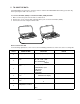
1. SPECIFICATIONS Memory Capacity Memory capacity differs according to model. The following shows the memory capacity for each available model. Model Memory SF-4700L 64K bytes SF-4900L 128K bytes The following shows the number or items that can be stored in each model (SF-4700L/4900L).
General: Display element: 16-column × 4-line LCD Main component: LSI Power supply: Three lithium batteries (CR2032) Current consumption: Telephone top menu (Backlight from EL doesn't shine)600 µA (MAX.) Telephone top menu (Backlight from EL shines)12.6 mA (MAX.) OFF- 19 µA (MAX.) Low battery message: 7.2 V ± 2.5% Forced power off: 6.7 V ± 2.5% Battery life: • Approximately 300 hours of continuous display only in Telephone Mode.
2. GENERAL GUIDE The following illustration shows the names of the main controls of the SF-4700L/4900L. Display Mode Keys Power OFF Key Power ON/ Clear key Numeric Keys Cursor Keys Connector Terminal Light key Keyboard Lock Setting Up the SF Unit After batteries are loaded, use the following procedures to set up the SF Unit for operation. To switch power on and off 1. Press ON to switch power on.
After a data error is discovered, you will not be able to input or edit data. In order to return memory to normal (allowing further input and editing of data), you must perform the RESET operation to clear the memory of all data. Before doing so, you may want to recall important data and write it down (if you don't already have a copy). You can then re-input the data after clearing the memory. The RESET procedure you should use depends on the type of message error message on the display.
To adjust the display contrast 1. • 2. 3. Enter the Telephone Directory Mode. You could enter any mode except the Calculator mode here. Press SHIFT CONT. Use the and keys to adjust the contrast. 4. After you are finished, press ESC to clear the contrast abjustment display. To select a mode Press one of the mode keys to select the mode you want. TEL Telephone Directory mode for storage of telephone numbers, name, addresses, and six user-definable entries.
3. BATTERY REPLACEMENT Before replacing the batteries, note the following precaution: • Be sure to replace all batteries with a full set of new ones, and do not mix old batteries with new ones. 1. Press OFF to switch power OFF. 2. Slide the battery compartment cover in the direction indicated by the arrow. +3 2 + 1 + 3. Slide the battery switch to the "REPLACE 1" setting. REPLACE +3 3 2 1 2 + 1 + NORMAL 4.
4. RESET OPERATION Warning! The following procedure erases all data stored in the memory of the SF Unit. Perform the following operation only when you want to delete all data and initialize the settings of the SF Unit. Remember-you should always keep copies of important data by writing it down, by transferring it to another SF-4700L (SF-4900L). To reset the SF Unit's memory 1. Press ON to switch power on. 2. Open the battery compartment and press the RESET button.
5. TO SAVE THE DATA SF-4700L/4900L can transfer the customer's data to another SF-4700L/4900L with memory protection only when replacing the LCD or the outer case. To connect SF-4700L (4900L) to another SF-4700L (4900L)CSF Unit 1. Make sure that the power of both units are switched off. 2. Remove the covers from the data communications jacks on the two SF-4700L (4900L). 3. Connect the two units using the SB-62 cable.
STEP 7 8 OPERATION DISPLAY NOTE Press [2] and then [TIME DATE] button on Unit 2. Press [3] and then [M+] button on Unit 2. 1901/ 2/ M SUN 1901/ 2/ 3 9 10 11 12 13 14 15 16 17 Press [TEL] button on Unit 2. Press [ON] button on Unit 1. 19 Mode display before power off Press [TEL] button on Unit 1. Press [FUNC] button on both Unit 1 and Unit 2. Press [FUNC] button on both Unit 1 and Unit 2. Press [4] button to select "4 DATA COMM"on both Unit 1 and Unit 2.
6. PIN FUNCTION CPU µPD3058Ap-009 : COB (Chip on Board) NOTE: The CPU is bonding on the PCB. If the CPU is defective, replace the PCB ASSY (A140745) because the CPU cannot be replaced. Pin No.
7. DIAGNOSTIC PROGRAM CAUTION:Performing this program, data saved in the Unit are disappeared (erased). Save these data to another SF-4700L(4900L) referring to 5. TO SAVE THE DATA. 3 2 Test Pad 1 Reset Button Bottom View To enter the diagnostic program, proceed as follows; 1 : Turn the power off, and then remove the battery cover. 2 : Press the power switch [ON] button while shorting the Test pad. STEP 1 OPERATION Press [ON] while shorting the Test pad. Press [set] button.
STEP 11 12 13 OPERATION Press [2] button to select "2 MEMORY". NOTE 3 WR2 4 READ2 1 WR1 5 DUMP 2 READ1 6 CHKSUM Press [1] button to select After displaying RAM WRITE1; "1 WR1". MEMORY 3 WR2 4 READ2 1 WR1 5 DUMP 2 READ1 6 CHKSUM After displaying EXECUTING!! Press [2] button to select "2 READ1". COMPLETE ! ! ✼✼ KB MEMORY Press [ESC] button. MEMORY Press [6] button to select "6 CHKSUM". 1 WR1 2 READ1 For example, TY SZ FE 0 128 Press [ESC] button. MEMORY 14 15 DISPLAY 16 Press [ESC] button.
STEP 21 OPERATION SEARCH, LEFT CURSOL KEY UP CURSOL KEY DOWN CURSOL KEY RIGHT CURSOL KEY ESC, Q, W E, R, T, Y U, I, O, P CAPS,SHIFT, Z, X D, F, G, H J, K, L, RETURN FUNC, SHIFT, Z, X C, V, B, N M, SPACE Press [set] button. Press [LIGHT] button. 23 25 32 Press [4] button to select "4 BUZZER". 34 35 36 37 38 39 40 44 48 52 56 60 64 42 46 50 54 58 62 66 69 43 47 51 55 59 63 67 41 45 49 53 57 61 65 68 After displaying 68 1 DISP TEST MENU 1 DISP BUZZER Press [2] button to select "2 ALARM".
STEP 29 OPERATION DISPLAY Press [1] buttons on Unit 1 to select "1 TRANS". NOTE Ready to transmit EXECUTING ! ! Press [2] buttons on Unit 2 to select "2 RECEIVE". Unit 1 indicates "EXECUTING". During the transmission 30 Unit 2 shows scrolling HHHHHH. 31 32 Press [ESC] button on Unit 1. Transmission completed TRANS BREAK ! ! Press [ON] button on Unit I/F 1 and 2. 1 2 3 4 7N9 33 Press [1] button on Unit 2 to select "1 TRANS".
8. ERROR MESSAGE Message Meaning Action NO DATA! Search operation attempted when no Current search operation cannot data is stored in memory. be performed. NOT FOUND! Data specified in search operation does not exist in memory. Change specification or cancel search. MEMORY FULL! No more room in memory for storage of data. Delete unnecessary data items from memory.
9.
Key Block — 20 —
10.
11. PARTS LIST N N N N N N N N N N N N N N N N N N N N N N N N N N N N N N Item Code No.
N Item N N 20 20 6420 6090 CASE/LOWER 6420 8350 CASE/LOWER A140695-1 A140695-2 1 made in 1 Malaysia N 20 6420 6280 CASE/LOWER A140695-4 1 made in Japan Notes: Code No. Parts Name N – New parts Q – Quantity used per unit R – Rank Specification B: A: F: E: — 23 — SF-4700L B.O.S.S SF-4700L Others SF-4900L B.O.S.S SF-4900L Others Q Available R–A: B: C: X: A/ E A/ E for U.S.A.
MA0900671A