
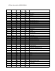
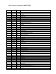
Specifications

— 18 —
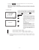
Pressing of the SEARCH key in either mode will return to the screen of the menu mode.
Sound can be stopped by pressing any key.
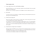
While an alarm is sounding the screen display is as shown left. If an irregularity is found in voltage
of battery while the alarm is sounding, the alarm will stop. After 256 seconds, the alarm will stop
automatically.
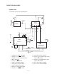
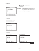
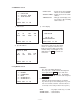
6. Interface check
The three charactors that appear on the right side at display
represent the parameter. In the case of the example display,
it indicates 7 BIT, NON PARITY, 9600 BPS. The operation
continues until stopped by pressing the ESC key and then
pressing the ON key for all modes.
DISP CHNG key : Return to menu mode
1 key : Transmission mode. The data of trans-
mission is "H" and it is sent out by the data
of H34 and H38 by the Xon/Xoff control.
2 key : Reception mode. Make sure to set the
parameter to match that of the transitting
side. The data received appears on the
display.
3 key : Output the following ASCII code by Xon/
Xoff control.
!"#*+,-/0123456789:
ABCDEFGHIJKLMNOPQRSTUVWXYZ
abcdefghijklmnopqrstuvwxyz
A line end code is added with each line.
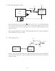
4 key : Loop back test. Short the Tx and Rx
terminals for this test. Transmit and check
from H20 to H7E. When complete, the
message 'CHECK COMPLETE' is dis-
played.
EXECUTING !
Parameter
MENU INTERFACE
1: DATA RECEIVE
2: DATA TRANSMIT
3: ASCII CODE
4: LOOP BACK
5:
7N9
CASIO 1993.11.09
6 key : Switch the data length 7 bit(7) or 8 bit(8)
7 key : Switch the parity bit : NON(N)—EVEN(E) —NON(N) —ODD(O)
8 key : Switch the transmission speed : 9600(9)—4800(4)—2400(2)—1200(1)
NOTE : As diagnostic program area does not have all ASCII code, to display a reception data, some
charactor will be changed to other charactor. For example, a capital letter will be changed
to small letter.