EN DATA PROJECTOR XJ-UT Series XJ-UT312WN*/ XJ-UT352W/XJ-UT352WN* XJ-F Series XJ-F11X/XJ-F21XN*/ XJ-F101W/XJ-F211WN* XJ-S Series XJ-S400U/XJ-S400UN*/ XJ-S400W/XJ-S400WN* *Network Models User’s Guide In this manual, “XJ-UT Series”, “XJ-F Series” and “XJ-S Series” refer only to the specific models listed above. Be sure to read the “Safety Precautions” and “Operating Precautions” and make sure you use this product correctly. Keep this manual in a safe place for future reference.
DLP is a registered trademark of Texas Instruments of the United States. Microsoft and Windows are registered trademarks or trademarks of Microsoft Corporation in the United States and other countries. HDMI, the HDMI Logo and High-Definition Multimedia Interface are trademarks or registered trademarks of HDMI Licensing Administrator, Inc. PJLink is a pending trademark or a registered trademark in Japan, the United States, and other countries and areas.
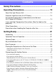
Contents Safety Precautions.......................................................... 7 Operating Precautions.................................................. 13 About the Light Source Unit .................................................................13 Projector Light Emission (XJ-UT Series) ..............................................13 Do not block light output or look directly into the lens! (XJ-F Series/XJ-S Series) .....................................................................
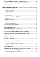
Cover Included with the YW-41 Wireless Adapter ...............................38 Attaching and Removing the Cable Cover (XJ-UT Series) ...................39 Remote Controller ................................................................................40 Operating the Projector................................................ 41 Turning the Projector On or Off ............................................................41 To turn on the projector ..........................................................
Using the Presentation Timer (TIMER) .................................................58 To display the timer ................................................................................................. 58 To display the timer function menu .......................................................................... 58 To configure timer settings....................................................................................... 58 Timer Operations .....................................................
Specifications ................................................................ 88 All Series...............................................................................................88 XJ-UT Series ........................................................................................89 XJ-F Series ...........................................................................................90 XJ-S Series...........................................................................................
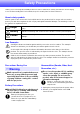
Safety Precautions Thank you for selecting this CASIO product. Be sure to read these “Safety Precautions” before trying to use it. After reading this User’s Guide, keep it in a safe place for future reference. About safety symbols Various symbols are used in this User’s Guide and on the product itself to ensure safe use, and to protect you and others against the risk of injury and against material damage. The meaning of each of the symbols is explained below.
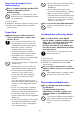
- Do not use the product if it is malfunctioning. • Do not subject a power cord to heat or attempt to modify it, and avoid damaging it. • Do not subject the power cord to excessive bending, twisting, or pulling. • Make sure the power cord is not pinched between the wall and the rack or table where the product is located, and never cover the power cord with a cushion or other object. Do not continue using the product if its display is abnormal or if it is malfunctioning.
Suffocation and Choking Risks Vent Blockage Do not allow anyone to play with the plastic bags used for product packaging. Do not allow blocking of the intake or exhaust vents. Be sure to observe the precautions below. - Plastic bags create the risk of suffocation when placed over the head, when swallowed, etc. Particular care is required in areas where young children are present.
Objects Blocking Projection Location Make sure there are no objects that can block the light in front of the lens while projecting. Do not place heavy objects on the product or climb up on it. - Such conditions create the risk of fire. Aquarium, Other Water Tank Make sure there is no aquarium or any other type of water tank that can produce a lens effect in front of the lens while projecting. - Such conditions create the risk of fire.
Do not use the product in the vicinity of high-precision electronic equipment or any electronic equipment that handles weak signals. YW-41 wireless adapter Keep the wireless adaptor out of the reach of small children. - Accidental swallowing of the wireless adaptor creates the risk of suffocation and personal injury.
Backup of important data + Other Be sure to keep separate written records of all data stored in projector memory. Memory data can be lost due to breakdown, maintenance, etc. Allowing dust to build up inside the projector by not cleaning it for long periods creates the risk of fire and accident, and can cause loss of projection luminosity. Contact your original dealer or authorized CASIO service center once a year about having the interior of the projector cleaned.
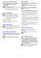
Operating Precautions About the Light Source Unit The projector’s light source unit uses a laser and LED. The life of the light source unit is rated at approximately 20,000 hours. The actual life will depend on use conditions, the settings configured on the setup menu, and differences between each individual light source unit. The light source unit is warranted for the period noted on the warranty certificate or for 6,000 hours, whichever comes first.
Do not block light output or look directly into the lens! (XJ-F Series/XJ-S Series) • Never block light output while the light is on. • Never look directly into the lens while the light is on. Particular care is required when children are present. ■ XJ-F Series Projection Lamp Caution This label is a “RISK GROUP 2” caution label required under the IEC62471 standard. RISK GROUP 2 (Moderate Risk) lamps exceed the limits of Exempt Group (No Hazard) standards.
Laser and High Temperature Precautions (See the label on the projector) Laser Precautions (Label , Label , Label , Label ) Non- U.S. Label : This projector is a Class 1 laser device that conforms to IEC 60825-1: 2014. U.S. Label : This projector is a Class 2 laser device that conforms to IEC 60825-1: 2007. U.S. Label , Label : This projector is a Class 3R laser device that conforms to IEC 60825-1: 2007. This projector has a built-in laser module.
XJ-F Series Label Wavelength : 445 nm Beam divergence : 60.7 mrad Pulse duration : – Maximum power or energy output : 40.
XJ-S Series Label Wavelength : 455 nm Beam divergence : 89 mrad Pulse duration : 1.2 ms (120 Hz) Maximum power or energy output : 59.
Other Precautions This projector is made of precision components. Failure to observe the following precautions can result in inability to correctly save data and malfunction. Never use or store the projector in the following locations. Doing so creates the risk of malfunction of and damage to the projector.
Never subject the projector to strong impact while it is projecting. If the projector is accidentally subjected to strong impact, the projection image will momentarily go blank. The image will reappear after some time, but it may be the wrong color or it may be accompanied by an error message. If the projected image is the wrong color, re-select the current input source. If this does not return the projected image to its proper color, turn projector power off and then back on again.
* Battery Precautions Observe the precautions below. Failure to do so can cause the battery to explode or leak flammable liquid or gas. Use only the type of battery that is specified for this product. Do not burn a battery or dispose of it in an incinerator, or by mechanical crushing or cutting. Do not subject a battery to excessively high or low temperatures during use, storage, or transport. Do not subject a battery to excessively low barometric pressure during use, storage, or transport.
Getting Ready Unpacking As you unpack the projector, check to make sure that all of the items listed below are present. Projector Wireless remote controller YT-161 Test Batteries (AAA-size × 2) AC Power Cord Cable cover (XJ-UT Series only) Wireless adapter YW-41 (XJ-UT312WN only) “Where to find the User’s Guide” sheet Warranty Operation Flow to Projection This section explains the operational flow up to the point that projection is started. 1.
7. Use the [INPUT] key to select the input source. “Selecting an Input Source (INPUT)” (page 42) 8. To adjust the projected image size, rotate the zoom ring (XJ-F Series/XJ-S Series). 9. Focus the image. XJ-UT Series: Slide the focus lever (page 23) upwards or downwards. XJ-F Series/XJ-S Series: Rotate the focus ring (page 23/page 24). 10. Perform keystone correction and adjust brightness as required.
General Guide XJ-UT Series Projection lens Speaker Control panel Remote control signal receiver Exhaust vents (left side) Indicators [P] key Brightness sensor Intake vents Intake vents AC Terminal Security bar Focus lever Terminals Security lock hole*1 XJ-F Series Key and indicator panel Remote control signal receiver Exhaust vents Security lock hole*1 Exhaust vents Intake vents Remote control signal receiver Zoom ring Projection lens Focus ring Intake vents 23 Speaker AC Terminal
XJ-S Series Exhaust vents Key and indicator panel Speaker Remote control signal receiver Security bar (bottom) AC Terminal Security lock hole*1 Intake vents Remote control signal receiver Zoom ring Intake vents Focus ring Projection lens *1 The anti-theft lock hole is provided for connection of an anti-theft chain. Visit the Kensington Lock Website at https://www.kensington.com/ for more information.
Key and Indicator Panel XJ-UT Series [MENU] key [ENTER] key [AUTO] key (XJ-UT Series) [INPUT] key [ON/Stand-by P] key [ESC] key Cursor keys (q/w/U/I) Brightness sensor TEMP indicator (XJ-UT Series) LIGHT indicator (XJ-UT Series) POWER/STANDBY indicator STATUS indicator (XJ-F Series/XJ-S Series) (2 (1 XJ-F Series (2 (3 XJ-S Series (2 (3 25
Back Terminals XJ-UT Series XJ-F Series (1 (2 (3 (4 (5(6 HDMI 2 terminal (XJ-UT352W / XJ-UT352WN) HDMI 1 terminal (XJ-UT352W / XJ-UT352WN) (7 HDMI terminal (XJ-UT312WN) COMPUTER IN 1 terminal MIC terminal AUDIO IN 1 terminal AUDIO IN 2 terminal USB-A/DC 5V port (XJ-UT312WN / XJ-UT352WN) DC 5V port (XJ-UT352W) LAN terminal (XJ-UT312WN / XJ-UT352WN) LOGO terminal (3 HDMI 2 terminal HDMI 1 terminal COMPUTER IN terminal USB
XJ-S Series (1 (2 (3 (4(5 (6 (7 COMPUTER IN 1 terminal (XJ-S400UN / XJ-S400WN) COMPUTER IN terminal (XJ-S400U / XJ-S400W) COMPUTER IN 2 terminal (XJ-S400UN / XJ-S400WN) MONITOR OUT terminal (XJ-S400UN / XJ-S400WN) AUDIO OUT terminal HDMI 1 terminal HDMI 2 terminal LOGO terminal USB-A/DC 5V port (XJ-S400UN / XJ-S400WN) DC 5V port (XJ-S400U / XJ-S400W) USB-A port (XJ-S400UN / XJ-S400WN) AUDIO IN 1 terminal (XJ-S400UN / XJ-S400WN) AUDIO IN terminal (XJ-S400U / XJ-
Placing the Projector on a Desk or on the Floor Locate the projector on a desk, table, or stand that is firm and level. Make sure that you allow sufficient space around the sides and back of the projector for proper ventilation. The illustrations below show how the projector should be oriented relative to the screen for optimum projection.
XJ-F Series Lift up the front of the projector and press the release button. This causes the front foot to drop from the bottom of the projector. While holding down the release button, raise and lower the front of the projector. When the front foot is the height you want, release the release button. The front foot will lock at that position. Make fine adjustments to the horizontal tilt of the projector by rotating the rear foot. Only one of the rear feet is adjustable to a height of ±3 mm.
Setup Precautions Use a conveniently located power outlet that you can reach easily when you need to unplug the projector. Airflow from air conditioning equipment can blow the heat being exhausted from the area around the projector’s lens in a way that causes heat ripples to appear in the projected image. If this happens, adjust the airflow of the air conditioning equipment or move the projector. XJ-UT Series Maintain a distance of at least 6 cm (2.
Connecting with Another Device Before starting projection, you first need to connect a computer, video device, and/or other devices to the projector. When selecting a cable, make sure that the shapes of its connectors match the shapes of the terminals on the projector and the devices being connected. Connecting a Computer Connect to the HDMI terminal or analog RGB terminal (VGA terminal) of the computer.
Analog RGB Connection With this type of connection, the RGB cable inputs only the image signal of the computer. If you also want to output audio from the computer, you will need to connect an audio cable. Projector Terminal Connection Cable COMPUTER IN 1*2 RGB cable (D-Sub 15-pin cable) or COMPUTER IN 2 Analog RGB Out (VGA) terminal 15-pin Mini D-Sub Audio cable AUDIO IN 1*3 or AUDIO IN 2 Computer Terminal Headphones jack or other audio output jack.
Component Video Connection Video device component video output terminals are grouped as a set of three: Y, Cb, Cr or Y, Pb, Pr. Connect the component video cable so the colors of its three plugs match the colors of the terminals (green for Y, blue for Cb or Pb, red for Cr or Pr). If you want to output the audio of the video device through the projector’s speaker, you also will need to connect an audio cable.
Outputting Audio from the Projector to Another Device You can output audio to an amp speaker or another device instead of using the projector’s built-in speaker. AUDIO OUT terminal AUDIO OUT terminal AUDIO OUT terminal XJ-UT Series XJ-F Series XJ-S Series Under initial projector default settings, audio is output from the projector’s built-in speaker. To output audio using another device, connect as shown below and then change the Setup Menu “Option Settings 2 3 Audio Out” setting to “Line”.
Connecting a Microphone (XJ-UT Series, XJ-F21XN, XJ-F211WN, XJ-S400UN, XJ-S400WN) Connecting a microphone to the projector’s MIC terminal makes it possible to output microphone input through the projector’s speaker. MIC terminal MIC terminal XJ-UT Series XJ-F21XN, XJ-F211WN MIC terminal XJ-S400UN, XJ-S400WN MIC terminal Mini jack Use this terminal to connect a dynamic microphone. Plug-in power type microphones are not supported.
Connecting a Wireless Adapter (Network Models Only) Connecting the projector’s wireless adapter* enables wireless connection to a computer or a smart device, or to an existing wireless access point. * The YW-41 wireless adapter may have been provided with your projector or may be available separately. See “Unpacking” (page 21). XJ-UT312WN, XJ-UT352WN XJ-F21XN, XJ-F211WN XJ-S400UN, XJ-S400WN XJ-UT312WN, XJ-UT352WN, XJ-S400UN, XJ-S400WN Plug into the USB-A/DC 5V port or the USB-A port.
Connecting a Scientific Calculator (Network Models Only) After connecting a scientific calculator to the projector, you will be able to project the calculator’s screen image. For information about connectable calculators, go to the CASIO website.
USB Power You can use the projector to supply USB power to another device. See “Supplying USB Power to Another Device” (page 76). Cover Included with the YW-41 Wireless Adapter The YW-41* wireless adapter comes with an anti-theft cover that can be installed on an XJ-F Series or XJ-S Series model. * The YW-41 wireless adapter may have been provided with your projector or may be available separately. See “Unpacking” (page 21).
Attaching and Removing the Cable Cover (XJ-UT Series) Before attaching or removing the cable cover, turn off the projector and unplug its power plug from the power outlet. After turning off the projector, wait for a while to allow it to cool. To attach the cable cover To remove the cable cover 1. Turn the projector over and insert the cable cover hook into the hole provided on the projector (Figure 1). 1. 2.
Remote Controller Projector operations are performed using the remote controller that comes with it. Point the remote controller signal emitter at one of the signal receivers on the projector as you perform remote controller key operations. The maximum range of the remote controller signal is approximately 5 meters (16.4 feet) (between signal emitter and receiver). Remote control signal emitter Turns power on or off. Press to exit the currently displayed menu or to cancel an operation.
Operating the Projector Unless specifically noted otherwise, the operations in this section are performed using the remote controller. If both the projector and the remote controller have the same key, either one can be used to perform the corresponding operation. Turning the Projector On or Off This section explains how to turn projector power on and off, and provides information about powerrelated settings.
Auto Power Off Under initial default settings, Auto Power Off is enabled and will automatically turn off the projector after about 10 minutes of non-operation (no key operation or input signal). You can use “Option Settings 1 3 Auto Power Off” (page 64) to change the Auto Power Off trigger time or to disable Auto Power Off. Auto Projection Off Auto Projection Off automatically turns off the projection light whenever the input signal from an input source is lost during projection.
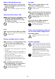
Using Auto Input Search After the projector is turned on, it starts an auto input search operation. It sequentially checks its image input terminals and, when it finds an input signal, it automatically starts projection of the signal’s image. Note Auto input search is not performed if “Test Pattern” is selected for “Screen Settings 3 No Signal Screen” (page 62). To trigger an auto input search operation manually 1. Hold down the [INPUT] key until the message “Searching...” appears on the display.
Auto Input Search Sequence Auto input search is performed in a particular sequence, depending on the projector model.
Changing the Input Source Manually Use the procedure below to change the input source manually. 1. Press the [INPUT] key to display the input menu. 2. Use the [INPUT], [], and [] keys to select the name of the input source you want, and then press the [ENTER] key. Note that even if you do not press the [ENTER] key, the projector will automatically switch to the input source you selected after about three seconds.
Changing the Audio Input Though the image input terminal of each input source is fixed, audio input terminal assignments can be changed by you as desired. To do this: Perform this operation: Change the audio input for a particular input source 1. Press the [MENU] key to display the Setup Menu. 2. Select the following in sequence, and then press the [ENTER] key: “Option Settings 2”, “Audio Input”. 3. Use the [] and [] keys to select the input source whose audio input setting you want to change. 4.
Using Auto Projection Off Auto Projection Off automatically turns off the projection light approximately 10 seconds*1 after the input signal from an input source is lost during projection. The light will turn back on if the input signal from the original input source is restored within 20 minutes*2 after the light is turned off. *1 A message first appears about five seconds after the input signal is lost, and then the light is turned off five seconds after that.
Enabling and Disabling Auto Projection Off Auto Projection Off is disabled under initial projector default settings. To enable Auto Projection Off, change “Screen Settings 3 Auto Projection Off” (page 62) on the Setup Menu to “Enable”.
Basic Image and Audio Operations During Projection To end the operations below, press the [ESC] key. To do this: Perform this operation: ■ XJ-UT Series Correct vertical and horizontal keystoning manually (KEYSTONE) 1. While there is no menu or dialog box displayed on the projection screen, press the projector [] or [] key, or the remote controller [KEYSTONE +] or [KEYSTONE –] key. 2. Use the [] and [] keys to correct vertical keystoning, and the [] and [] keys to correct horizontal keystoning.
To do this: Perform this operation: Change the aspect ratio of the projected image (ASPECT) 1. Press the [ASPECT] key. Each press of the [ASPECT] key cycles between the aspect ratio settings as shown below. For the meaning of each setting, see “Aspect Ratio Setting Details” (page 51).
Aspect Ratio Setting Details Normal Projects at the projector’s maximum possible size while maintaining the input signal aspect ratio. Full Projects at the projector’s maximum possible size by enlarging or reducing the input signal. 16:9 This setting specifies a 16:9 aspect ratio, which is the same as a movie screen, high-definition TV, etc. Using this setting when the input signal is a 16:9 image that has been squeezed to a 4:3 image causes the image to be displayed with its normal 16:9 aspect ratio.
Light Control Light Control lets you adjust the light being output (light source brightness) by the projector. When “On” is selected for “Option Settings 1 3 Light Control 3 Light Control” (page 64) on the Setup Menu (initial default setting), light output can be adjusted to one of seven levels. To do this: Perform this operation: Adjust light output 1. While there is no menu or dialog box displayed on the projection screen, press the [] or [] key.
Digital Screen Shift You can use the procedures in this section to reduce the size of the projected image while maintaining its aspect ratio and to shift the projection image vertically or horizontally, without physically moving the projector. To do this: Perform this operation: Adjust the projection image size and position 1. Press the [MENU] key to display the setup menu. 2.
4. To stop template projection, change to another input source or turn off the projector. Note Note that an image input signal being input to the projector cannot be projected while a template is being projected. Auto Projection Off (page 47) and Auto Power Off (page 64) are both disabled while a template is being projected.
Test Pattern Projection You can use the operations below to have the projector project a “No Signal Screen” (page 62) or a “Blank Screen” (page 62) as a test pattern. Use the test pattern when adjusting the parameters of the projection screen (position, size, keystone correction, focus, aspect ratio, Digital Screen Shift, etc.) The test pattern also comes in handy when making fine adjustments after mounting the projector on a wall.
Configuring Remote Control ID and Projector ID Settings The remote control ID and projector ID are numbers from 1 to 4. If the two IDs match, you will be able to perform all projector operations from the remote controller. This function helps to avoid remote control conflicts when there are multiple projectors (up to four) in the same area.
Countdown Timer and Remote Controller Keys The four buttons underneath the countdown timer correspond to remote controller buttons as shown below. Countdown Timer Operations The operations below can be performed while the countdown timer is shown. To do this: Perform this operation: Specify the countdown start time 1. While the countdown is stopped, press the [FUNC] key. This displays the countdown time setting screen. 2. Use the [] and [] keys to move the cursor to the digit you want to change. 3.
Using the Presentation Timer (TIMER) The presentation time shows the time remaining for a presentation. Under initial default settings, the presentation timer is displayed discreetly in the lower right corner of the projection screen. Important! To use the presentation timer, change “Option Settings 2 3 Timer Type” (page 65) on the Setup Menu to “Presentation”. To display the timer When the timer is not displayed on the projected image, press the [TIMER] key once.
Timer Operations Perform all of the operations below while the timer function menu (page 58) is displayed. To do this: Perform this operation: Start a countdown timer operation Select “Start Timer” and then press the [ENTER] key. This will close the timer function menu and start the timer countdown. After the countdown reaches 00:00, it will start a 60-minute count up operation (from –00:01 to –60:00).
Using the Setup Menu (MENU) Pressing the [MENU] key displays the Setup Menu on the projection screen. You can use this menu to adjust projected image brightness, contrast, and other settings, and to change projector settings. Setup Menu Settings One or more letters (such as RCV) after the menu item name indicates an item that is available only when one or more particular input source is selected. The letters indicate the input source(s) where the menu item is available.
Use this menu item: To do this: Image Adjustment 2 3 Vertical Position (RCV) Adjust the vertical and horizontal positions of the input source image in relation to the target screen. Image Adjustment 2 3 Horizontal Position (RCV) Image Adjustment 2 3 Frequency (R) Adjust the frequency setting manually. Adjust manually when vertical bands appear in the projected image while RGB is selected as the input source, which means that the frequency setting is not correct.
Use this menu item: To do this: Screen Settings 3 Projection Mode Specify whether projection will be from the front of the screen or the back of the screen. Front*: Select this option to project from the front of the screen. Rear: Select this option to project from the back of the screen. This setting flips the front projected image horizontally. Screen Settings 3 Ceiling Mount Set up the projector to be positioned upside down for mounting on a wall.
Use this menu item: To do this: Input Settings 3 COMPUTER Terminal (XJ-F Series/XJ-S400U/ XJ-S400W) Specify the method to be used to identify the COMPUTER IN terminal input signal. Auto*: Signal input to the COMPUTER IN terminal is identified automatically. RGB: Signal input to the COMPUTER IN terminal is always assumed to be an RGB signal. Component: Signal input to the COMPUTER IN terminal is always assumed to be a component video signal.
Use this menu item: To do this: Option Settings 1 3 Light Control 3 Light Sensor Enable or disable the light sensor. On: Enables automatic adjustment of light output in accordance with surrounding light. Off*: Disables automatic adjustment of light output. Option Settings 1 3 Light Control 3 Light Control Enable or disable projector light output (light source brightness). On*: Enables light output adjustment. Off: Disables light output adjustment and “Light Sensor” (above).
Use this menu item: To do this: Option Settings 2 3 Control Panel Lock Disable projector unit key operations. See “Control Panel Lock” (page 55) for more information. Option Settings 2 3 Standby RGB/Audio (XJ-UT Series/XJ-S400UN/ XJ-S400WN) Specify output of projector image input to the MONITOR OUT terminal and input audio to the AUDIO OUT terminal while the projector is in standby (projector off with power being supplied).
Use this menu item: To do this: Network 3 Network Settings 3 Wireless LAN Function N Toggle the projector’s wireless LAN function between “Enable”* and “Disable”. Network Settings*1 3 Network Settings 3 Remote On Specify whether the projector can be turned on via wired LAN while the projector is in standby (projector off with power being supplied). Enable: Remote on enabled. Disable*: Remote on disabled. Projector standby power consumption depends on whether or not “Remote On” is enabled.
Using a Password You can use the procedure in this section to password protect projector operations. You can have only one password assigned to the projector at any time, and the same password is used for operations. Power On Password Protection Turning on the projector will display a dialog box prompting input of the password.
Using the Password Feature Note the following precautions whenever you use the password feature. The password feature protects against unauthorized use of the projector. Note that it is not an antitheft measure. You will need to enter the initial factory default password the first time you use the projector after turning on the password feature. Change the initial factory default password to a different one of your choice as soon as possible after turning on the password feature.
Cleaning the Projector Make it a habit to clean the projector at regular intervals as described in this section. Before cleaning the projector, be sure to unplug it from the power outlet and make sure it is cooled down completely. Cleaning the Projector Exterior Wipe the exterior of the projector with a soft cloth that has been moistened in a weak solution of water and a mild neutral detergent. Be sure to wring all excess moisture from the cloth before wiping.
Troubleshooting Normal Operation Indicators The color and on/off/flashing status of the indicators let you know the current operational status of the projector. The table below shows what the indicators look like when operation is normal.
Error Indicators and Messages Important! If you turn off power or if power turns off automatically after an error occurs, first confirm that the projector’s fan is stopped. After the fan stops, unplug the power cord. An error will not be cleared if you unplug the power cord while the fan is running. Error Messages Error Messages Description and Required Action Internal temperature is too high. Check projector air vents for blockage. (POWER/STANDBY indicator lights green.
System Errors and Other Operation Problems XJ-UT Series XJ-F Series, XJ-S Series POWER : Lit red POWER : Lit red LIGHT : – STATUS : Lit red TEMP : Lit red The projector was automatically turned off because of a system problem or because of an operational problem caused by external noise. After confirming that the POWER/STANDBY indicator is lit red (without flashing), disconnect the power cord from the projector and wait for all of the projector’s indicators to go out.
Projector Troubleshooting Check the following items whenever you experience any problem with the projector. Problem Cause and Recommended Action Power does not turn on. If the POWER/STANDBY indicator is not lit, the AC power cord is not connected correctly. Connect the AC power cord correctly. If the TEMP or LIGHT indicator (XJ-UT Series models), or the STATUS indicator (XJ-F Series and XJ-S Series models) remains flashing or lit, it means that some type of error has occurred.
Problem Cause and Recommended Action Text is blurry. The image may be out of focus. Adjust image focus. The current frequency and/or phase setting do not match the input signal. (Applies only when the input source is an RGB signal.) Press the [AUTO] key to execute an automatic adjustment operation. On the setup menu, perform the “Image Adjustment 2 3 Frequency” and “Image Adjustment 2 3 Phase” adjustments. (Applies only when the input source is an RGB signal.
Checking the Serial Number and Board Number Each projector is assigned a unique serial number and board (circuit board) number to identify it. You can find these numbers at the locations shown below. Serial Number The serial number is shown on label affixed to the projector.
Appendix Supplying USB Power to Another Device The terminals in the table below can be used to supply USB power to another device. Model Name XJ-UT312WN, XJ-UT352WN, XJ-S400UN, XJ-S400WN Terminal Name USB-A/DC 5V port USB-A port Power/Current DC 5V/1.5A DC 5V/0.5A XJ-F21XN, XJ-F211WN USB-A/DC 5V port DC 5V/2A XJ-UT352W, XJ-F11X, XJ-F101W, XJ-S400U, XJ-S400W DC 5V port DC 5V/2A Important! Turning off projector power also cuts power being supplied to external equipment.
Mounting the Projector on a Wall (XJ-UT Series) You can use special wall mounting hardware to mount the projector on a wall. In this configuration, the projector should be mounted with the top of the projector downwards. For full details, contact the retailer where you purchased the projector. Important! When mounting the projector on a wall, make sure that it is at least one meter away from fire detectors, fire alarms, and other fire protection devices.
Using the MONITOR OUT Terminal (XJ-UT Series, XJ-S400UN, XJ-S400WN) The MONITOR OUT terminal of the projector outputs the video signal being input via the COMPUTER IN 1 terminal or COMPUTER IN 2 terminal as-is. This makes it possible to simultaneously output the projection image to another display. Note The signals output from the MONITOR OUT terminal when the projector is turned on depends on the selected input source as shown in the table below.
Projection Distance and Screen Size The projection distance values below are for reference when setting up the projector. XJ-UT Series h L Projection Size Projection Distance (Distance to projector front): L (cm / inch) Height from Projector Bottom to Screen Bottom: h (cm / inch) Screen Size Diagonal (cm) 50 127 6 / 2.4 24 / 9.4 60 152 13 / 5.1 27 / 10.6 80 203 27 / 10.6 32 / 12.6 100 254 40 / 15.7 38 / 15 110 279 47 / 18.5 40 / 15.
XJ-F Series h Approximate Projection Distance Projection Size XJ-F11X/XJ-F21XN B XJ-F101W/XJ-F211WN Screen Size Diagonal (cm) Minimum Distance (m / feet) Maximum Distance (m / feet) h Minimum Distance (m / feet) Maximum Distance (m / feet) 30 76 0.93 / 3.05 1.38 / 4.53 0 – – – 35 89 – – – 0.92 / 3.02 1.37 / 4.49 8 / 3.15 40 102 1.27 / 4.17 1.88 / 6.17 0 1.06 / 3.48 1.58 / 5.18 9 / 3.54 60 152 1.95 / 6.4 2.87 / 9.42 0 1.64 / 5.38 2.42 / 7.94 13 / 5.
XJ-S Series h Approximate Projection Distance Projection Size XJ-S400U/XJ-S400UN Diagonal (cm) Minimum Distance (m / feet) Maximum Distance (m / feet) 30 76 0.77 / 2.53 40 102 1.06 / 3.48 60 152 77 196 80 h (cm / inch) Maximum Distance (m / feet) h (cm / inch) 1.34 / 4.40 7 / 2.76 0.80 / 2.62 1.41 / 4.63 6 / 2.36 1.82 / 5.97 9 / 3.54 1.10 / 3.61 1.91 / 6.27 8 / 3.15 1.64 / 5.38 2.78 / 9.12 14 / 5.51 1.70 / 5.58 2.92 / 9.58 12 / 4.72 2.13 / 6.99 3.59 / 11.78 17 / 6.69 2.
Aspect Ratio Setting and Projection Image The following shows how images are projected in accordance with the type of the input signal and the aspect ratio setting of the projector.
XGA models (1024 × 768) Input source: RGB, HDMI(PC), CASIO USB Tool, Network or Templates Input Signal Normal Full 16:9 16:10 16:10 4:3 SVGA (800 × 600) XGA (1024 × 768) WXGA (1280 × 800) SXGA (1280 × 1024) Input source: Video, Component or HDMI(DTV) Input Signal Normal 16:9 4:3 Aspect Image Squeezed Image Letter Box Image 16:9 Aspect Image 83
Supported Signals RGB (VESA) 640 × 480/60 Component (HDTV) 640 × 480/72 1080p/60 640 × 480/75 720p/50 640 × 480/85 720p/60 800 × 600/56 1080i/50 800 × 600/60 1080i/60 800 × 600/72 Component (SDTV) 800 × 600/75 800 × 600/85 576p/50 576i/50 480p/60 1024 × 768/60 480i/60 1024 × 768/70 Video 1080p/50 HDMI 640 × 480/60 1024 × 768/75 800 × 600/60 1024 × 768/85 1024 × 768/60 1152 × 864/75 1280 × 720/60 1280 × 720/60 1280 × 768/60 1280 × 768/60 1280 × 800/60 1280 × 800/60 1280 × 9
Projector RS-232C Control To control the projector using RS-232C commands from a computer, you need to connect the projector and computer using a commercially available serial cable (cross).
Command List While the projector is turned off, it can receive only following commands: check power on/off state (PWR?), read light time (LMP?), and write power on (PWR1). Do not try to send any other commands to the projector while it is turned off. Input of a valid signal must be in progress in order to use a command to turn on blank screen or change the aspect ratio. You can use only the commands and settings that are equipped on your projector model.
Command Name Function Settings POS Setup Type*7 0: Projection with top of projector upwards, screen in front 1: Projection with top of projector downwards, screen in back 2: Projection with top of projector upwards, screen in back 3: Projection with top of projector downwards, screen in front APO Auto Power Off 0: Off, 1: 5 minutes, 2: 10 minutes, 3: 15 minutes, 4: 20 minutes 5: 30 minutes STS R Reads the projector error status.
Specifications All Series DLP® chip × 1, DLP® system Display system Light Source Laser and LED Gamut Full color (up to 1.
XJ-UT Series Model Name Display Chip XJ-UT312WN Chip Size XJ-UT352W XJ-UT352WN WXGA 0.65 inches (Aspect ratio: 16:10) Number of Pixels 1,024,000 (1280 × 800) Projection Lens Fixed zoom, manual focus F 2.3 / f 4.2 Projected Image Size Projection Distance 50 to 110 inches 60 inches 0.13 meters (0.4 feet) 100 inches 0.40 meters (1.3 feet) Minimum Projection Distance 0.06 meters (0.
XJ-F Series Model Name Display Chip Chip Size Number of Pixels XJ-F11X XJ-F21XN XJ-F101W XJ-F211WN XGA 0.55 inches (Aspect ratio: 4:3) WXGA 0.65 inches (Aspect ratio: 16:10) 786,432 (1024 × 768) 1,024,000 (1280 × 800) Projection Lens 1.5X manual zoom, manual focus F 2.31 to 2.73 / f 18.9 to 27.2 Projected Image Size Projection Distance 30 to 300 inches 35 to 300 inches 60 inches 1.95 to 2.87 meters (6.4 to 9.4 feet) 1.64 to 2.42 meters (5.4 to 7.9 feet) 100 inches 3.33 to 4.85 meters (10.
Model Name XJ-F11X XJ-F21XN XJ-F101W XJ-F211WN Standby Power Consumption (220 to 240V) When “Disable” is specified for “Remote On” *5 0.23W When “Enable” is specified for “Remote On” *5 0.8W (Network models only) Approximate Dimensions 299 (W) × 299 (D) × 97 (H) mm (11.8" × 11.8" × 3.8") (Including projections) Approximate Weight 3.8kg (8.4lbs) XJ-S Series Model Name Display Chip Chip Size Number of Pixels XJ-S400U XJ-S400UN XJ-S400W XJ-S400WN WUXGA 0.
Model Name XJ-S400U XJ-S400UN XJ-S400W XJ-S400WN Light Output 7 when “Light Control” is “On” 210W 215W 210W 215W Light Output 1 when “Light Control” is “On” 120W 125W 120W 125W When “Bright” is selected for “Light Control Off Mode” 250W 255W 250W 255W When “Normal” is selected for “Light Control Off Mode” 215W 220W 215W 220W Power Consumption (100 to 240V) Standby Power Consumption (100 to 120V) When “Disable” is specified for “Remote On” *5 0.
GUIDELINES LAID DOWN BY FCC RULES FOR USE OF THIS UNIT IN THE U.S.A. (not applicable to other areas). NOTICE This equipment has been tested and found to comply with the limits for a Class B digital device, pursuant to Part 15 of the FCC Rules. These limits are designed to provide reasonable protection against harmful interference in a residential installation.
GPL and LGPL (1) This product uses software (This Software) that comes under the GNU General Public License (GPL) and GNU Lesser General Public License (LGPL). In accordance with the GPL and LGPL, the source code of This Software is open source code. Anyone who wishes to view the open source code can do so by downloading it from the CASIO Projector download site. Whenever copying, modifying, or distributing This Software, be sure to do so in accordance with the terms and conditions of the GPL and LGPL.
MA2102-D