XW-P1/XW-G1 MIDI Implementation CASIO COMPUTER CO., LTD. Contents I MIDI Message Overview 1 9 Product Configuration as a MIDI Device 9 1.1 System Section . . . . . . . . . . . . . . . . . . . . . . . . . . . . . . . . . . . . . . . . . . 9 1.2 Performance Controller Section . . . . . . . . . . . . . . . . . . . . . . . . . . . . . . . . . 9 1.3 Sound Generator Section . . . . . . . . . . . . . . . . . . . . . . . . . . . . . . . . . . . .
8 7.11 Sostenuto (42H) . . . . . . . . . . . . . . . . . . . . . . . . . . . . . . . . . . . . . . . . . 16 7.12 Soft (43H) . . . . . . . . . . . . . . . . . . . . . . . . . . . . . . . . . . . . . . . . . . . . 16 7.13 Drawbar Position 16’(46H)(Drawbar tone selected) . . . . . . . . . . . . . . . . . . . . . . 16 7.14 Filter Resonance(47H) . . . . . . . . . . . . . . . . . . . . . . . . . . . . . . . . . . . . . . 16 7.15 Drawbar Position 5 1/3’(47H)(Drawbar tone selected) . . . . . . . . . .
9 Channel After Touch 37 10 Pitch Bend 37 III System Message 39 11 Timing Clock 39 12 Start 39 13 Stop 39 14 Active Sensing 39 15 System Exclusive Message 40 15.1 Universal Real Time System Exclusive Message . . . . . . . . . . . . . . . . . . . . . . . . 40 15.2 Universal Non Real Time System Exclusive Message . . . . . . . . . . . . . . . . . . . . . 42 15.3 Instrument-Specific System Exclusive Message . . . . . . . . . . . . . . . . . . . . . . . .
21 Patch Parameter 66 21.1 Analog Input Tune Parameter . . . . . . . . . . . . . . . . . . . . . . . . . . . . . . . . . 66 21.2 Card Audio Parameter . . . . . . . . . . . . . . . . . . . . . . . . . . . . . . . . . . . . . 66 21.3 DSP Output Parameter . . . . . . . . . . . . . . . . . . . . . . . . . . . . . . . . . . . . . 66 21.4 DSP Setup Parameter . . . . . . . . . . . . . . . . . . . . . . . . . . . . . . . . . . . . . . 66 21.5 Master EQ Parameter . . . . . . . . . . . . . . . . . .
28 User Wave Parameter(XW-G1 only) 80 28.1 User Wave Key Splits Parameter (x10splits) . . . . . . . . . . . . . . . . . . . . . . . . . 80 28.2 User Wave LFO Parameter . . . . . . . . . . . . . . . . . . . . . . . . . . . . . . . . . . . 80 28.3 User Wave Looper Parameter . . . . . . . . . . . . . . . . . . . . . . . . . . . . . . . . . . 81 DSP Parameter 81 DSP Basic . . . . . . . . . . . . . . . . . . . . . . . . . . . . . . . . . . . . . . . . . . . .
38.5 Solo Synth Chorus . . . . . . . . . . . . . . . . . . . . . . . . . . . . . . . . . . . . . . . . 89 38.6 Solo Synth Delay . . . . . . . . . . . . . . . . . . . . . . . . . . . . . . . . . . . . . . . . . 89 38.7 Solo Synth Ring Modulator . . . . . . . . . . . . . . . . . . . . . . . . . . . . . . . . . . . 90 38.8 Wah . . . . . . . . . . . . . . . . . . . . . . . . . . . . . . . . . . . . . . . . . . . . . . . . 90 38.9 Compressor . . . . . . . . . . . . . . . . . . . . . . . . . . . . .
38.45 Flanger Reflection . . . . . . . . . . . . . . . . . . . . . . . . . . . . . . . . . . . . . . . . 99 38.46 Flanger Auto Pan . . . . . . . . . . . . . . . . . . . . . . . . . . . . . . . . . . . . . . . . 99 38.47 Reflection Distortion . . . . . . . . . . . . . . . . . . . . . . . . . . . . . . . . . . . . . . . 100 38.48 Reflection Chorus . . . . . . . . . . . . . . . . . . . . . . . . . . . . . . . . . . . . . . . . 100 38.49 Reflection Auto Pan . . . . . . . . . . . . . . . . . . . . . . . . . . .
39.27 Synth Ext Osc Pitch Shifter Mix Setting Value Table . . . . . . . . . . . . . . . . . . . . 107 39.28 Synth LFO Wave Setting Value Table . . . . . . . . . . . . . . . . . . . . . . . . . . . . . 108 39.29 Synth LFO Sync Setting Value Table . . . . . . . . . . . . . . . . . . . . . . . . . . . . . 108 39.30 Synth LFO Clock Sync Setting Value Table . . . . . . . . . . . . . . . . . . . . . . . . . . 108 39.31 Synth Total Filter Type Setting Value Table . . . . . . . . . . . . . . . . . . . . . . . . .
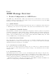
Part I MIDI Message Overview 1 Product Configuration as a MIDI Device As a MIDI device, this Instrument consists of the System Section, Sound Generator Section, and Performance Controller Section described below. Each of these sections can send and receive specific MIDI Messages in accordance with its function. 1.1 System Section The System Section manages the Instrument status and user data.
Part number 01 MIDI Receive Ch 01-16 MIDI Send Ch 01-16 02 03 04 05 01-16 01-16 01-16 01-16 01-16 01-16 01-16 01-16 Zone 2/SMF play/MIDI IN 06 01-16 01-16 Multi-function Phrase 2(Note1)/SMF play/MIDI IN 07 08 09 10 11 12 13 14 15 16 01-16 01-16 01-16 01-16 01-16 01-16 01-16 01-16 01-16 01-16 01-16 01-16 01-16 01-16 01-16 01-16 01-16 01-16 01-16 01-16 Guide on/Precount on/SMF play/MIDI IN Note 2 : Assigned Function Zone 1/Step Sequencer(Solo 1)/Multi-function Phrase 1(Note1)/SMF play/MIDI I
Part II Channel Message MIDI Message Send by Assignable Knobs When the Instrument is in the Performance Mode, any control change, after touch, or other MIDI message from CC:00H to CC:65H can be assigned to the assignable knobs, so the MIDI messages are sent by knob operation. For details about the functions that can be assigned, see the User’s Guide.
7 Control Change Message Format: n: cc: vv: BnH ccH vvH MIDI Channel Number Control Number Value Drawbar Operation by Control Change Message When a drawbar tone is selected on the applicable MIDI channel (n: MIDI Channel Number), control change messages can be used to perform various drawbar parameter operations. (Drawbar tone selection is supported by the XW-P1 only.
Receive Receipt causes a change in the tone bank number stored in Instrument memory, but the tone is not actually changed until a Program Change message is received. For details, see “8 Program Change”. The performance number and Step Sequencer number can also be changed by the bank program. For details, see “8 Performance Number/Step Sequencer Number Switching by Bank Select Message and Program Change Message”. For details about performance and the Step Sequencer, see the User’s Guide. 7.
Send Sent when the mixer part volume is changed. Receive Receipt changes the mixer part volume. 7.6 Pan (0AH) Message Format: n: vv: Note1 : BnH 0AH vvH MIDI Channel Number Value(Note1) For information about the relationship between setting values and send/receive values, see “39.3 Pan Setting Value Table” in “VIII Setting Values and Send/Receive Values”. Send Sent when the pan of any part is changed. Receive Receipt changes the pan of the corresponding part. 7.
Received values and parameter setting values The range of the value of each DSP Parameter 7 array element depends on the selected DSP or array number. Unlike manipulation of a DSP parameter using a System Exclusive Message, a value received by this control change message is always in the range of 0 to 127, but the range is changed in accordance with the setting range of the applicable parameter setting. Because of this, it is impossible for a value to be outside of the range.
7.11 Sostenuto (42H) Message Format: n: vv: : Note1 BnH 42H vvH MIDI Channel Number Value (Note1) For information about the relationship between setting values and send/receive values, see the “39.1 Off/On Setting Value Table” in “VIII Setting Values and Send/Receive Values” of this document. Send Sent when a pedal that has a sostenuto function is operated. Receive Receipt performs an operation equivalent to a sostenuto pedal operation. 7.
7.15 Note Drawbar Position 5 1/3’(47H)(Drawbar tone selected) : This message is valid only when a drawbar tone is selected for the MIDI channel. Message Format: n: vv: : Note1 BnH 47H vvH MIDI Channel Number Value (Note1) For information about the relationship between setting values and send/receive values, see the “39.5 Drawbar Position Setting Value Table” in “VIII Setting Values and Send/Receive Values” of this document. Send Sent when a drawbar 5 1/3’ is operated.
: Note1 For information about the relationship between setting values and send/receive values, see the “39.2 –64 - 0 - +63 Setting Value Table” in “VIII Setting Values and Send/Receive Values” of this document. Receive Receipt makes a relative change in the time it takes for a note to rise to its maximum level. 7.19 Note Drawbar Position 4’(49H)(Drawbar tone selected) : This message is valid only when a drawbar tone is selected for the MIDI channel.
7.22 Note Drawbar Position 2’(4BH)(Drawbar tone selected) : This message is valid only when a drawbar tone is selected for the MIDI channel. Message Format: n: vv: : Note1 BnH 4BH vvH MIDI Channel Number Value (Note1) For information about the relationship between setting values and send/receive values, see the “39.5 Drawbar Position Setting Value Table” in “VIII Setting Values and Send/Receive Values” of this document. Send Sent when a drawbar 2’ is operated.
: Note1 For information about the relationship between setting values and send/receive values, see the “39.2 –64 - 0 - +63 Setting Value Table” in “VIII Setting Values and Send/Receive Values” of this document. Receive Receipt changes the degree of pitch modulation. 7.26 Note Drawbar Position 1 1/3’(4DH)(Drawbar tone selected) : This message is valid only when a drawbar tone is selected for the MIDI channel.
7.29 Note Drawbar Organ Type(4FH)(Drawbar tone selected) : This message is valid only when a drawbar tone is selected for the MIDI channel. Message Format: n: vv: : Note1 BnH 4FH vvH MIDI Channel Number Value (Note1) For information about the relationship between setting values and send/receive values, see the “39.6 Sine/Vintage Setting Value Table” in “VIII Setting Values and Send/Receive Values” of this document. Receive Receipt changes the drawbar parameter type. 7.
Receive Receipt changes the percussion decay time. 7.33 Note Drawbar Organ Key On Click(57H)(Drawbar tone selected.) : This message is valid only when a drawbar tone is selected for the MIDI channel. Message Format: n: vv: : Note1 BnH 57H vvH MIDI Channel Number Value (Note1) For information about the relationship between setting values and send/receive values, see the “39.1 Off/On Setting Value Table” in “VIII Setting Values and Send/Receive Values” of this document.
Note1 : For information about the relationship between setting values and send/receive values, see the “39.2 –64 - 0 - +63 Setting Value Table” in “VIII Setting Values and Send/Receive Values” of this document. Receive Receipt changes the degree of pitch modulation. 7.37 Reverb Send (5BH) Message Format: n: vv: BnH 5BH vvH MIDI Channel Number Value Send Sent when the reverb send of any part is changed. Receive Receipt changes the reverb send of the corresponding part. 7.
Receive Receipt changes the mixer part on/off setting. 7.39.2 DSP Enable Message Format: n: mm: ll: Note1 : BnH 62H 01H BnH 63H 22H BnH 06H mmH BnH 26H llH MIDI Channel Number Value (Note1) (Send:00H, Receive:Ignored) For information about the relationship between setting values and send/receive values, see the “39.1 Off/On Setting Value Table” in “VIII Setting Values and Send/Receive Values” of this document. Send Sent when a mixer part DSP on/off setting is changed.
Receive Receipt while S.Seq NRPN is enabled by Instrument settings changes the Step Sequencer number. 7.39.5 Step Sequencer Pattern Number Select Message Format: n: mm: ll: BnH 62H 01H BnH 63H 25H BnH 06H mmH BnH 26H llH MIDI Channel Number Value (Note1) (Send:00H、Receive:Ignored) Send Sent when the Step Sequencer pattern is changed while S.Seq NRPN is enabled by Instrument settings. Receive Receipt while S.Seq NRPN is enabled by Instrument settings changes the Step Sequencer pattern is changed. 7.39.
Receive Receipt while Phrase NRPN is enabled by Instrument settings changes the Phrase Sequencer number. 7.39.8 Phrase Sequencer Start/Stop Message Format: n: mm: ll: BnH 62H 01H BnH 63H 26H BnH 06H mmH BnH 26H llH MIDI Channel Number Value (Note1) (Send:00H、Receive:Ignored) Send Sent when the Phrase Sequencer is started or stopped while Phrase NRPN is enabled by Instrument settings. Receive Receipt while Phrase NRPN is enabled by Instrument settings starts or stops the Phrase Sequencer. 7.39.
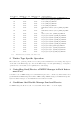
Note1 ff 00 01 02 03 04 05 06 07 08 : The following shows the relationship between the Drawbar Foot value and the actual foot bar. Foot Bar Ft16’ Ft5 1/3’ Ft8’ Ft4’ Ft2 2/3’ Ft2’ Ft1 3/5’ Ft1 1/3’ Ft1’ Note2 : For information about the relationship between setting values and send/receive values, see the “39.5 Drawbar Position Setting Value Table” in “VIII Setting Values and Send/Receive Values” of this document.
7.39.13 Drawbar Organ 3rd Percussion Message Format: n: mm: ll: Note1 : BnH 62H 0BH BnH 63H 40H BnH 06H mmH BnH 26H llH MIDI Channel Number Value (Note1) (Send:00H, Receive:Ignored) For information about the relationship between setting values and send/receive values, see the “39.1 Off/On Setting Value Table” in “VIII Setting Values and Send/Receive Values” of this document. Receive Receipt changes the drawbar parameter 3rd percussion (XW-P1 only). 7.39.
7.39.16 Drawbar Organ Key Off Click Message Format: n: mm: ll: Note1 : BnH 62H 0EH BnH 63H 40H BnH 06H mmH BnH 26H llH MIDI Channel Number Value (Note1) (Not sent, Receive:Ignored) For information about the relationship between setting values and send/receive values, see the “39.6 Sine/Vintage Setting Value Table” in “VIII Setting Values and Send/Receive Values” of this document. Receive Receipt changes the drawbar key off click (XW-P1 only). 7.39.
Parameter pitch envelope attack level pitch envelope decay time pitch envelope sustain level pitch envelope release1 time pitch envelope release1 level pitch envelope release2 time pitch envelope release2 level pitch envelope clock trigger pitch envelope depth pitch key follow pitch key follow base filter cutoff filter gain filter touch sensitivity filter key follow filter key follow base filter lfo depth 1 filter lfo depth 2 filter envelope init level filter envelope attack time filter envelope attack leve
Parameter amp envelope attack level amp envelope decay time amp envelope sustain level amp envelope release1 time amp envelope release1 level amp envelope release2 time amp envelope release2 level amp envelope clock trigger pwm pulse width pwm lfo depth 1 pwm lfo depth 2 Synth sync osc Synth ext osc original key Synth ext osc pitch eg trigger Synth ext osc filter eg trigger Synth ext osc amp eg trigger Synth ext osc total filter eg trigger Synth ext osc mic inst level Synth ext osc noise gate threshold Synt
Note6 : For information about the relationship between setting values and send/receive values, see the “39.25 Filter Gain Setting Value Table” in “VIII Setting Values and Send/Receive Values” of this document. Note7 : For information about the relationship between setting values and send/receive values, see the “39.26 Synth Ext Osc Pitch Shifter Mode Setting Value Table” in “VIII Setting Values and Send/Receive Values” of this document.
Note1 : For information about the relationship between setting values and send/receive values, see the “39.31 Synth Total Filter Type Setting Value Table” in “VIII Setting Values and Send/Receive Values” of this document. Note2 : For information about the relationship between setting values and send/receive values, see the “39.21 –128 - 0 - +127 Setting Value Table” in “VIII Setting Values and Send/Receive Values” of this document.
Message Format: n: ll: mm: 7.40.1 BnH 64H llH (LSB) BnH 65H mmH (MSB) MIDI Channel Number LSB Value MSB Value Pitch Bend Sensitivity Message Format: n: mm: ll: BnH 64H 00H BnH 65H 00H BnH 06H mmH BnH 26H llH MIDI Channel Number MSB Value(00H - 18H) LSB Value(Send:00H, Receive:Ignored) Send Sent when Bend Range of any part is changed. Receive Receipt changes Bend Range of the corresponding part. 7.40.
Receive Receipt changes the coarse tune of the corresponding part. Does not affect sound source operation when the Timbre Type (see “About the Timbre Type” in “8 Program Change”) is Drum. 7.40.4 Null Message Format: n: BnH 64H 7FH BnH 65H 7FH MIDI Channel Number Send Sent when an RPN, NRPN message send operation is performed. Receive Receipt de-selects RPN, NRPN. 7.41 All Sound Off (78H) Message Format: n: BnH 78H 00H MIDI Channel Number Receive Receipt stops all voices that are sounding. 7.
7.45 Omni On (7DH) Message Format: n: BnH 7DH 00H MIDI Channel Number Receive Receipt performs the same operation as when All Notes Off is received. 7.46 Mono (7EH) Message Format: n: BnH 7EH 00H MIDI Channel Number Receive Receipt performs the same operation as when All Notes Off is received. 7.47 Poly (7FH) Message Format: n: BnH 7FH 00H MIDI Channel Number Receive Receipt performs the same operation as when All Notes Off is received.
• Drum This setting optimizes for drum sounds. The damper pedal does not function. The Hold1, Channel Coarse Tune, and Master Coarse Tune messages are ignored if they are received. • Drawbar(XW-P1 only) This setting optimizes for drawbar tones. The damper pedal performs on/off operations. • Hex Layer(XW-P1 only) This setting optimizes for hex layer tones. The damper pedal performs on/off operations. • Solo Synth This setting optimizes for solo synth tones. The damper pedal performs on/off operations.
Send Sent when the bender is operated. Receive Receipt changes the pitch of the currently sounding note. The range of the pitch change depends on the Bend Range value setting.
Part III System Message 11 Timing Clock Message Format: F8H Send Sent periodically when the MIDI syn mode is master. Receive Receipt while the MIDI sync mode is slave causes tempo to be synced based in timing clock information. 12 Start Message Format: FAH Send Sent when the Step Sequencer is started while the MIDI sync mode is master. Receive Receipt while the MIDI sync mode is slave starts Auto Accompaniment play upon receipt of the next sent timing clock (F8H).
15 System Exclusive Message Message Format: ii: dd: F0H iiH ddH....F7H ID Number Device ID The Instrument sends and receives standard universal system exclusive messages, and system exclusive messages that have Instrument-specific formats. ID Number ID Number 44H 7EH 7FH The ID numbers handed by this Instrument are shown below. ID Name Casio Computer Co.
Send Sent when the Master Pan is changed. Receive Receipt changes the Master Pan. 15.1.3 Master Fine Tuning Message Format: dd: ll: mm: Note1 : F0H 7FH ddH 04H 03H llH mmH F7H Device ID LSB Value(Note1) MSB Value(Note1) For information about the relationship between setting values and send/receive values, see “39.4 Fine Tuning Setting Value Table” in “VIII Setting Values and Send/Receive Values” of this document. Send This message is sent when the tuning setting is changed.
Receive Receipt changes the Chorus Sent To Reverb setting. 15.2 Universal Non Real Time System Exclusive Message Message Format: dd: 15.2.1 F0H 7EH ddH....F7H Device ID GM System On Message Format: dd: F0H 7EH ddH 09H 01H F7H Device ID Receive Receipt puts the sound source into a GM sound source mode. 15.2.2 GM System Off Message Format: dd: F0H 7EH ddH 09H 02H F7H Device ID Receive Receipt changes the sound source setting to the Instrument presetting. 15.2.
Part IV Instrument-Specific System Exclusive Messages 16 Format This section explains the format of the Instrument-specific System Exclusive Messages. See “V Parameter List” and “VI Parameter Set List” for information about how parameter sets actually are transferred. 16.1 Message Classifications Basically, the operation that corresponds to Instrument-specific system exclusive messages is parameter data transfer.
16.2 Basic Message Structure Instrument-specific system exclusive message operation can be broadly divided between two methods: Individual Parameter Transfer (single parameter send/receive) and Bulk Parameter Set Transfer (batch parameter send/receive). Each method includes a number of different messages. The field in the system exclusive message that specifies the message type is the action (act) field. The format of the body part of the message depends on the act value.
16.3.4 dev : MIDI Device ID 00H - 7FH Format: 0dddddddB The contents of this field in a received message are compared with the Model’s MIDI Device ID, and receipt of the incoming message is allowed only when the two IDs match. When a message containing 7FH is received, receipt of the message is always allowed, regardless of the Instrument’s ID setting. 16.3.5 act : Action Format: 0aaaaaaaB This field indicates the operation of the Instrument-specific System Exclusive Message.
HBS:Handshake Bulk Parameter Set Send Indicates a parameter set image send message using handshake mode. The parameter set to be transferred is divided into multiple packets when it is greater than a prescribed size. The packets are transferred in accordance with handshake mode. EXI:Extend Interval During a dump session, message sent by a devices that should send the next message to tell a device waiting for the next message to extend the message interval.
Category ID (c) Parameter Set 00H System 02H Patch 03H Tone 05H Melody 06H Drum 07H Drawbar(XW-P1 only) 08H Hex Layer(XW-P1 only) 09H Solo Synth 0AH User Wave(XW-G1 only) 13H DSP 1FH All 26H Step Sequencer 27H Step Sequencer Chain 28H Arpeggio 29H Phrase 2AH Spec Transfer Individual Parameter A A A A A A A A A A F F F F F A One-way Bulk A A A A A A A A A A A A A A A Handshake Bulk A A A A A A A A A A A A A A A A · · · Available (Also including when only some parameters are available.
Format: Note : index3 index3 index2 index2 index1 index1 index0 index0 LSB MSB LSB MSB LSB MSB LSB MSB 0iiiiiiiB 0jjjjjjjB 0kkkkkkkB 0lllllllB 0mmmmmmmB 0nnnnnnnB 0oooooooB 0pppppppB Arranged in high dimension sequence.
The Parameter ID indicates the parameter type. When transferring parameters (see “V Parameter List” below) individually (as opposed to bulk transfer), this field is used to identify the parameter being transferred by its parameter ID. 16.3.11 Format: idx : Data Index Number LSB MSB 0iiiiiiiB 0jjjjjjjB The data index number indicates the first array number of the array from which transfer starts. 16.3.
data0: data1: data2: data3: data4: 7 0 0 0 0 0 6 [bit06] [bit13] [bit20] [bit27] 0 5 [bit05] [bit12] [bit19] [bit26] 0 4 [bit04] [bit11] [bit18] [bit25] 0 3 [bit03] [bit10] [bit17] [bit24] [bit31] 2 [bit02] [bit09] [bit16] [bit23] [bit30] 1 [bit01] [bit08] [bit15] [bit22] [bit29] 0 [bit00] [bit07] [bit14] [bit21] [bit28] SBS (Start of Bulk Dump Session) Format: 0bbbbbbbB The relationship between the data value and error 0bbbbbbB is defined as shown below.
16.3.14 Format: img : Parameter Set Memory Image Data0 Data1 Data2 Data3 : 0aaaaaaaB 0bbbbbbaB 0cccccbbB 0ddddcccB : During data transfer, the memory image data of the parameter set to be sent is read sequentially in 1-byte units starting from the first address. That value is transformed starting from the lower bit to a 7-bit wide data string.
crc : Cyclic Redundancy Check 16.3.15 Format: LSB MSB 0aaaaaaaB 0bbbbbbaB 0cccccbbB 0ddddcccB 0000ddddB CRC32 (in accordance with ISO 8802-3 or IEEE803.2 regulations) 32-bit value (ddddddddccccccccbbbbbbbbaaaaaaaaB) calculated for the byte string from “MAN: Manufacturer’s ID” to the last byte of “img: Parameter Set Memory Image” is stored in this “crc: Cyclic Redundancy Check”. The receiving unit checks the value, and if it is not correct sends an error as a re-request. 16.3.
With the one-way mode, the sending device sends data and ends the session without regard to the response of the receiving device. This mode is best for one-way transfers from a sequencer or similar device. With the handshake mode, the sending device sends the data and then waits for a response from the receiving device before advancing to the next session. This is a high-speed mode in which there is no time wasted waiting. See “VI Parameter Set List” for details about Instrument parameter sets. 18.1.
Data Receiver (External Device) SBS(OBR) Data Sender (This Instrument) -----> <----Interval 2 *Note2 <----Interval 2 *Note2 <----: Send Other Packet : <----- OBS Send Request (Start Sub Session) Send Packet OBS Send Packet OBS Send Packet ESS End of Data (End Sub Session) : Other Sub Session : -----> EBS Note1 Session Start Request Interval 1 *Note1 -----> OBR : Operation End of Session Interval 1 is no less than Oneway Min Interval and no more than Oneway Max Interval, which are explaine
Data Sender (External Device) SBS(OBS) -----> Interval *Note -----> Interval *Note -----> Interval *Note : Send Other Packet : -----> <----: Other Sub Session : -----> OBS OBS ESS EBS : Operation Session Start Request Interval *Note -----> OBS Note Data Receiver (This Instrument) Send Packet (Start Sub Session) Send Packet Send Packet ACK End Sub Session End of Session The interval is no less than Oneway Min Interval and less than Oneway Max Interval, which are explained under “20.
RJC is sent and the session is terminated. The number of retries is determined in accordance with the parameters described under “20.2 System Exclusive Protocol Parameter”. 18.3.4 Message CRC Error Processing The message receive device returns ERR (CRC Error) if it discovers an illegal format in the received message. When the sending device receives ERR (CRC Error) from the receiving device, it resends the last data sent.
Data Receiver (External Device) SBS(HBR) -----> <---------> ACK HBR <---------> <---------> <---------> : Send Other Packet : -----> <----- HBS ACK ACK ACK ACK HBS HBS ESS EBS HBS ESS Operation Session Start Request Acknowledge Send Request (Start Sub Session) Send Packet Acknowledge Send Packet Acknowledge Send Packet Acknowledge Acknowledge End Data (End Sub Session) End of Session Example: Data send to Instrument from external device Data Sender (External Device) SBS(HBS) HBS HBS : Ot
18.3.
Data Receiver (External Device) SBS(HBR) HBR ACK ERR(Format Error) ACK ACK ACK Data Sender (This Instrument) -----> <---------> <---------> <-???-----> <-----???-> <-----???-> <---------> <----: Note1 : Note2 : ACK HBS HBS HBS ERR(Format Error) ERR(Format Error) HBS Operation Session Start Request Acknowledge Send Request (Optional) Send Packet Acknowledge Send Packet (Note1) Format Error Resend Packet Acknowledge Format Error Acknowledge 2 consecutive format errors(*Note2) Acknowledge Send Packe
Note : Number of retries that exceeds the retries stipulated by Handshake Max Retry explained under “20.2 System Exclusive Protocol Parameter”. 18.3.
Data Sender (External Device) SBS(HBS) HBS HBS HBS 18.3.15 Data Receiver (This Instrument) -----> <---------> <---------> <---------> <----- Operation Session Start Request Acknowledge Send Packet Acknowledge Send Packet Acknowledge Send Packet Terminate Session ACK ACK ACK RJC Example: Session Pause Session flow when the session is temporarily paused for some reason and then restarted is shown below.
Note2 : The sessions can be paused by sending RJC here.
Part V Parameter List This section explains the parameters that actually can be transferred by the Instrument. 19 Using the Parameter List • Parameter field Shows the parameter name. • ID field Shows the parameter ID as a hexadecimal number. • R/W field Shows “R” to indicate that an IPR (Individual Parameter Request) read operation (Read) is possible or “W” to indicate that an IPS (Individual Parameter Send) write operation is possible. • Block field Shows the bit field allocation of the block number.
20.2 System Exclusive Protocol Parameter These parameters are related to the System Exclusive message protocol.
Parameter Current Sub Ps Size ID R/W 0020 R Block ↑ Current Ps Name 0021 R ↑ Max Ps Size 0022 R ↑ Max Ps Number 0023 R ↑ Area Size 0024 R ↑ Available Size 0025 R ↑ Free Size 0026 R ↑ Delete Ps 0027 W ↑ Bulksession Enabled 0028 R ↑ Size Array Min-Def-Max Description 32 01 00000000-00000000-FFFFFFFF Total size of a parameter sets under the specified category (bytes). 8 10 00-20-7F Name of a parameter set in the specified category (ASCII characters).
21 Patch Parameter The main function of patch parameters is to configure the settings of the sound source of a device. 21.1 Analog Input Tune Parameter These parameters are for analog input tuning. Parameter Part Enable ID R/W Block Size Array Min-Def-Max Description 0074 R/W 00000000 1 01 00-01-01 0...Off 1...On Line Select 0075 R/W ↑ 1 01 00-00-01 0...System Chorus 1...
Parameter Low Gain Low Frequency ID R/W Block Size Array Min-Def-Max Description 008D R/W 00000000 8 01 00-0C-18 -12 - 0 - +12 008E R/W 00000000 8 01 00-01-02 0...200Hz 1...400Hz 2...800Hz Lowmid Gain 008F R/W 00000000 8 01 00-0C-18 -12 - 0 - +12 Lowmid Frequency 0090 R/W 00000000 8 01 00-01-07 0...1.0kHz 1...1.3kHz 2...1.6kHz 3...2.0kHz 4...2.5kHz 5...3.2kHz 6...4.0kHz 7...5.0kHz Highmid Gain 0091 R/W 00000000 8 01 00-0C-18 -12 - 0 - +12 Highmid Frequency 0092 R/W 00000000 8 01 00-06-07 0...1.0kHz 1...1.
Parameter Cho Send Rev Send Bend Range Line Select 21.9 ID 006F 0070 0071 0072 R/W R/W R/W R/W R/W Block ↑ ↑ ↑ ↑ Size Array 7 01 7 01 7 01 1 01 Min-Def-Max 00-00-7F 00-28-7F 00-02-18 00-00-01 Description 0 - 127 0 - 127 0 - 24 0...System Chorus 1...DSP System Chorus Parameter These parameters ar for configuring system chorus settings. Parameter Level Rate Sendtorev 21.
Parameter Arpeggio Hold ID R/W 00AA R/W Block ↑ Arpeggio StepSeq Sync 00AB R/W ↑ Phrase Key Play 00AC R/W 00000000 Phrase Phrase Phrase Looper Enable 00AD 00AE 00AF 00B1 00B2 R/W R/W R/W R/W R/W ↑ ↑ ↑ ↑ 00000000 Lowkey Target Index1 Index2 Index3 Zone Enable 00B3 00B4 00B5 00B6 00B7 00B8 R/W R/W R/W R/W R/W R/W ↑ 4-0:TargetType 5-0:KeySetting ↑ ↑ 2-0:Zone(0-3) Zone Zone Zone Zone Zone Zone Zone 00B9 00BA 00BB 00BC 00BD 00BE 00BF R/W R/W R/W R/W R/W R/W R/W ↑ ↑ ↑ ↑ ↑ ↑ ↑ Zone Knob2 Enabl
Parameter ID R/W Block Size Array Min-Def-Max Description Timbre Num 0002 R/W ↑ 14 01 0000-0000-3FFF 0 - 16383 Line Select 0004 R/W ↑ 1 01 00-00-01 0...System Chorus 1...DSP Timbre Type 0006 R/W ↑ 4 01 00-00-0F 0...Melody 1...Piano 2...Drum 3...Drawbar(XW-P1 only) 4...Hex Layer(XW-P1 only) 5...Solo Synth 6...User Wave(XW-G1 only) Name 0007 R/W ↑ 7 10 00-20-7F Ascii Character Level 0008 R/W ↑ 7 01 00-7F-7F 0 - 127 23 Melody Parameter These parameters configure melody tone settings. 23.
24.2 Velocity Split Parameter (x4velocity-split x128instrument) These parameters are for configuring velocity split for each drum tone instrument. Parameter ID R/W Range Top 0007 R/W Number 24.3 0008 R/W Block Size Array Min-Def-Max Description 13-7:Inst 7 01 00-7F-7F Velocity upper limit value 2-0:Split ↑ 14 01 0000-0000-3FFF Inst number 0-376 LFO Parameter These parameters configure drum tone LFO settings.
Parameter ID Keyoff Click 0004 R/W ↑ Type 0005 R/W ↑ Vibrato Rate Vibrato Depth 0006 R/W 0007 R/W ↑ ↑ 26 R/W Block Size Array Min-Def-Max Description 1...on 1 01 00-00-01 0...off 1...on 1 01 00-00-01 0...Normal 1...Vintage 7 01 00-00-7F 0 - 127 7 01 00-00-7F 0 - 127 Hex Layer Parameter(XW-P1 only) These parameters configure hex layer tone settings. 26.1 Hex Layer Parameter (x6layer) These parameters configure basic hex layer tone settings.
Parameter ID R/W Block Pitch Pitch Pitch Pitch Pitch 0016 0017 0018 0019 001A R/W R/W R/W R/W R/W ↑ ↑ ↑ ↑ ↑ Pitch After Depth 001B R/W ↑ Amp LFO Wave Type 001C R/W ↑ Amp Amp Amp Amp Amp 001D 001E 001F 0020 0021 R/W R/W R/W R/W R/W ↑ ↑ ↑ ↑ ↑ Amp LFO After Depth 0022 R/W ↑ 27 LFO Rate Auto Delay Auto Rise Auto Depth Mod Depth LFO LFO LFO LFO LFO Rate Auto Delay Auto Rise Auto Depth Mod Depth Size Array Min-Def-Max Description 5...Pulse 2:2 6...
Parameter LFO Depth Pitch Key Cent ID R/W Block Size Array Min-Def-Max Description 0008 R/W ↑ 7 02 00-40-7F -64 - 0 - +63 0009 R/W ↑ 16 01 0000-0000-FFFF S------.- -------- S:sign bit -ssssss.- -------- s:semitone(semitone) -------.c cccccccc c:cent = 100/512 cent resolution 0000000.0 00000000...original 0001100.0 00000000...For +1 octave 1110100.0 00000000...For -1 octave 0000001.0 00000000...For +100 cent(1 semitone) 1111111.0 00000000...For -100 cent(1 semitone) 0000000.1 00000000...
Parameter Attack Time Attack Level Decay Time Sustain Level Release1 Time Release1 Level Release2 Time Release2 Level Clock Trigger Envelope Depth 27.4 ID 0020 0021 0022 0023 0024 0025 0026 0027 0028 R/W Block Size Array Min-Def-Max Description R/W ↑ 7 01 00-00-7F 0 - 127 R/W ↑ 7 01 00-00-7F 0 - 127 R/W ↑ 7 01 00-00-7F 0 - 127 R/W ↑ 7 01 00-00-7F 0 - 127 R/W ↑ 7 01 00-00-7F 0 - 127 R/W ↑ 7 01 00-00-7F 0 - 127 R/W ↑ 7 01 00-00-7F 0 - 127 R/W ↑ 7 01 00-00-7F 0 - 127 R/W ↑ 7 01 00-00-12 0...OFF 1...
Parameter 27.5 ID R/W Block Size Array Min-Def-Max Description 15...3/2 up beat 16...2 up beat 17...3 up beat 18...4 up beat Solo Synth Etc (x8controller) These parameters configure other Solo Synth settings. Parameter Sync Osc ID R/W Block Size Array Min-Def-Max Description 003D R/W 00000000 1 01 00-00-01 0...Async 1...Sync OSC2 with OSC1 Ext OSC Original Key 003E R/W ↑ 7 01 00-3C-7F 0 - 127 Pitch Eg Trigger 003F R/W ↑ 1 01 00-00-01 0...off 1...on Filter Eg Trigger 0040 R/W ↑ 1 01 00-00-01 0...off 1..
Destination Parameter Parameter Name 06H OSC Pitch Envelope Init Level 07H OSC Pitch Envelope Attack Time 08H OSC Pitch Envelope Attack Level 09H OSC Pitch Envelope Decay Time 0AH OSC Pitch Envelope Sustain Level 0BH OSC Pitch Envelope Release1 Time 0CH OSC Pitch Envelope Release1 Level 0DH OSC Pitch Envelope Release2 Time 0EH OSC Pitch Envelope Release2 Level 0FH OSC Pitch LFO1 Depth 10H OSC Pitch LFO2 Depth 11H OSC PWM Pulse Width 12H OSC PWM LFO1 Depth 13H OSC PWM LFO2 Depth 14H OSC Ext Original Key 15H
Destination Parameter Parameter Name 47H Total Filter LFO2 Depth 48H LFO Rate 49H LFO Depth 4AH LFO Delay 4BH LFO Rise 4CH LFO Modulation Depth 4DH DSP Parameter1 4EH DSP Parameter2 4FH DSP Parameter3 50H DSP Parameter4 51H DSP Parameter5 52H DSP Parameter6 53H DSP Parameter7 54H DSP Parameter8 55H OSC S1-P2 Portamento Time 56H OSC S1-P2 Init Level 57H OSC S1-P2 Attack Time 58H OSC S1-P2 Attack Time 59H OSC S1-P2 Decay Time 5AH OSC S1-P2 Sustain Level 5BH OSC S1-P2 Release1 Time 5CH OSC S1-P2 Release1 Level
Parameter ID R/W Modulation Depth 0062 R/W 27.8 Block ↑ Size Array Min-Def-Max Description 7 01 00-00-7F 0 - 127 Solo Synth PWM These parameters configure Solo Synth PWM settings. Parameter ID R/W Block Size Array Min-Def-Max Description Pulse Width 003A R/W 0:Oscillator Number 7 01 00-00-7F 0 - 127 Available selected PWM as Synth Wave. LFO Depth 003C R/W ↑ 7 02 00-40-7F -64 - 0 - +63 27.9 Solo Synth Total Filter These parameters configure Solo Synth Total Filter settings.
28 User Wave Parameter(XW-G1 only) These parameters configure User Wave tone settings. 28.1 User Wave Key Splits Parameter (x10splits) These parameters configure User Wave tone split settings.
Parameter Pitch Mod Depth ID R/W 0024 R/W Block ↑ Pitch After Depth 0025 R/W ↑ Amp LFO Wave Type 0026 R/W ↑ Amp Amp Amp Amp Amp 0027 0028 0029 002A 002B R/W R/W R/W R/W R/W ↑ ↑ ↑ ↑ ↑ Amp LFO After Depth 002C R/W ↑ LFO LFO LFO LFO LFO 28.3 Rate Auto Delay Auto Rise Auto Depth Mod Depth Size Array Min-Def-Max Description 7 01 00-40-7F 0 - 127 (effective:-64 7 01 00-40-7F 0 - 127 (effective:-64 4 01 00-00-0F 0...Sin 1...Tri 2...Saw Up 3...Saw Down 4...Pulse 1:3 5...Pulse 2:2 6...
Parameter ID R/W Block Size Array Min-Def-Max Description Size 0001 R 000000 32 01 00000000-00000000-00FFFFFF 0 - 0xFFFFFFFF 31 31.1 Step Sequencer Parameter Step Sequencer Directory Info The Step Sequencer parameter stores Step Sequencer data directory information. Parameter ID R/W Block Size Array Min-Def-Max Description Name 0000 R 00000000 7 10 20-20-7F Ascii Character Size 0002 R 000000 32 01 00000000-00000000-00FFFFFF 0 - 0xFFFFFFFF 32 32.
Parameter Perform Filter ID R/W 0001 R/W Block ↑ Size Array Min-Def-Max Description 16 01 0000-0030-FFFF bit0: Step Seq bit1: Arpeggio bit2: Phrase bit3: Tempo bit4: System Reverb bit5: System Chorus bit6: System Master EQ Setting Start Up Select 0002 R/W ↑ 2 01 00-00-02 0...Patch 1...Tone 2...Step Seq Chain Number 0003 R/W ↑ 8 01 00-00-63 0 - 99 Setting Fine Tune 0004 R/W ↑ 10 01 010B-0200-0303 -245 - 259 (415.5Hz 465.
Parameter Looper Channel ID R/W 0050 R/W Block ↑ Size Array 1 01 Looper Fs 0051 R/W ↑ 1 01 00-01-01 Looper Auto Overdub 0052 R/W ↑ 1 01 00-00-01 84 Min-Def-Max 00-00-01 Description 0: Mono 1: Stereo 0: 21kHz 1: 42kHz 0: Off 1: On
Part VI Parameter Set List This section explains actually how parameter sets can be transferred by the Instrument with bulk dump. 36 Parameter Set Table Field Contents • cat field Shows the category value.(Note1) • mem field Shows the memory area ID value.(Note1) • pset field Shows the parameter set number value. Applicable parameter set numbers are those in the user area where the top number is zero, and are not the same numbers as those displayed by the Instrument. (Note1) : Note1 36.
36.
Part VII DSP Parameter List 37 DSP Type List This is a list of DSP types built into the Instrument. 37.1 Solo Synth DSP Solo Synth DSP Number 01 02 03 04 05 06 07 37.2 37.2.
37.2.2 Dual DSP Normal DSP Number 15 16 17 18 19 20 21 22 23 24 25 26 27 28 29 20 31 32 33 34 35 36 37 38 39 30 41 42 43 44 45 46 38 38.
Parameter Number Parameter7[1] Parameter7[2] Parameter7[3] Parameter7[4] Note1 : Parameter Name LFOWaveform LFO Rate LFO Depth Manual Value 00 - 7F 00 - 7F 00 - 7F 00 - 7F Notes Note1 Note2 For information about the relationship between setting values and send/receive values, see “39.15 LFO Wave Form3 Setting Value Table” in “VIII Setting Values and Send/Receive Values” of this document. Note2 : For information about the relationship between setting values and send/receive values, see the “39.
Note3 : For information about the relationship between setting values and send/receive values, see “39.7 Tempo Sync Setting Value Table” in “VIII Setting Values and Send/Receive Values” of this document. 38.7 Solo Synth Ring Modulator Parameter Number Parameter7[1] Parameter7[2] Parameter7[3] 38.
Note1 : For information about the relationship between setting values and send/receive values, see “39.15 LFO Wave Form3 Setting Value Table” in “VIII Setting Values and Send/Receive Values” of this document. Note2 : For information about the relationship between setting values and send/receive values, see the “39.2 –64 - 0 - +63 Setting Value Table” in “VIII Setting Values and Send/Receive Values” of this document. 38.
38.17 Delay Parameter Number Parameter7[1] Parameter7[2] Parameter7[3] Parameter7[4] Parameter7[5] Parameter7[6] Parameter7[7] Note1 : Parameter Name Delay Time Feedback Ratio Lch Ratio Rch Wet Level Type Tempo Sync Value 00 - 7F 00 - 7F 00 - 7F 00 - 7F 00 - 7F 00 - 7F 00 - 7F Notes Note1 Note2 Note3 Note4 For information about the relationship between setting values and send/receive values, see “39.
38.20 Ring Modulator Parameter Number Parameter7[1] Parameter7[2] Parameter7[3] Parameter7[4] Note1 : Parameter Name OSC Freq LFO Rate LFO Depth Type Value 00 - 7F 00 - 7F 00 - 7F 00 - 7F Notes Note1 For information about the relationship between setting values and send/receive values, see “39.18 Ring Type Setting Value Table” in “VIII Setting Values and Send/Receive Values” of this document. 38.
Note1 : For information about the relationship between setting values and send/receive values, see “39.13 LFO Wave Form1 Setting Value Table” in “VIII Setting Values and Send/Receive Values” of this document. 38.
Parameter Number Parameter7[1] Parameter7[2] Parameter7[3] Parameter7[4] Parameter7[5] Parameter7[6] Note1 : Parameter Name WahWaveform Wah Rate Wah Depth TrmWaveform Trm Rate Trm Depth Value 00 - 7F 00 - 7F 00 - 7F 00 - 7F 00 - 7F 00 - 7F Notes Note1 Note2 For information about the relationship between setting values and send/receive values, see “39.13 LFO Wave Form1 Setting Value Table” in “VIII Setting Values and Send/Receive Values” of this document.
38.31 Compressor Chorus Parameter Number Parameter7[1] Parameter7[2] Parameter7[3] Parameter7[4] Parameter7[5] Note1 : Parameter Name Cmp Thresh Cmp Level ChoWaveform Cho Rate Cho Depth Value 00 - 7F 00 - 7F 00 - 7F 00 - 7F 00 - 7F Notes Note1 For information about the relationship between setting values and send/receive values, see “39.15 LFO Wave Form3 Setting Value Table” in “VIII Setting Values and Send/Receive Values” of this document. 38.
Note1 : For information about the relationship between setting values and send/receive values, see “39.15 LFO Wave Form3 Setting Value Table” in “VIII Setting Values and Send/Receive Values” of this document. Note2 : For information about the relationship between setting values and send/receive values, see the “39.2 –64 - 0 - +63 Setting Value Table” in “VIII Setting Values and Send/Receive Values” of this document. 38.
38.40 Distortion Reflection Parameter Number Parameter7[1] Parameter7[2] Parameter7[3] 38.
Parameter Number Parameter7[1] Parameter7[2] Parameter7[3] Parameter7[4] Parameter7[5] Parameter7[6] Parameter7[7] Note1 : Parameter Name ChoWaveform Cho Rate Cho Depth PanWaveform Pan Rate Pan Depth Pan Manual Value 00 - 7F 00 - 7F 00 - 7F 00 - 7F 00 - 7F 00 - 7F 00 - 7F Notes Note1 Note2 Note3 For information about the relationship between setting values and send/receive values, see “39.15 LFO Wave Form3 Setting Value Table” in “VIII Setting Values and Send/Receive Values” of this document.
38.47 Reflection Distortion Parameter Number Parameter7[1] Parameter7[2] Parameter7[3] 38.48 Value 00 - 7F 00 - 7F 00 - 7F Notes Value 00 - 7F 00 - 7F 00 - 7F 00 - 7F Notes Reflection Chorus Parameter Number Parameter7[1] Parameter7[2] Parameter7[3] Parameter7[4] Note1 Parameter Name RefFeedback Dst Gain Dst Level : Parameter Name RefFeedback ChoWaveform Cho Rate Cho Depth Note1 For information about the relationship between setting values and send/receive values, see “39.
Note1 : For information about the relationship between setting values and send/receive values, see “39.15 LFO Wave Form3 Setting Value Table” in “VIII Setting Values and Send/Receive Values” of this document. Note2 : For information about the relationship between setting values and send/receive values, see “39.15 LFO Wave Form3 Setting Value Table” in “VIII Setting Values and Send/Receive Values” of this document. 38.
Part VIII Setting Values and Send/ Receive Values 39 39.1 Setting Value Tables Off/On Setting Value Table Transmit Value 00H 7FH 39.2 Receive Value 00H : 40H : 7FH Parameter -64 : 0 : +63 Pan Setting Value Table Transmit Value 00H : 40H : 7FH 39.4 Parameter Off On –64 - 0 - +63 Setting Value Table Transmit Value 00H : 40H : 7FH 39.
39.5 Drawbar Position 設定値テーブル Transmit Value 00H 14H 28H 32H 3cH 50H 5AH 6EH 7FH 39.6 Parameter Sine Vintage Receive Value 00H - 0AH 0BH - 16H 17H - 21H 22H - 2DH 2EH - 39H 3AH - 44H 45H - 50H 51H - 5CH 5DH - 67H 68H - 73H 74H - 7FH Parameter Off 1/4 1/3 3/8 1/2 2/3 3/4 1 4/3 3/2 2 0-3 Setting Value Table Transmit Value 00H 2AH 55H 7FH 39.9 Receive Value 00H - 3FH 40H - 7FH Tempo Sync Setting Value Table Transmit Value 00H 0CH 19H 26H 33H 40H 4CH 59H 66H 73H 7FH 39.
39.10 Chorus Mode Setting Value Table Transmit Value 00H 40H 7FH 39.11 Parameter determined by Delay Time determined by Delay Time and Ratio L/R Receive Value 00H - 1FH 20H - 3FH 40H - 5FH 60H - 7FH Parameter off sin tri random Receive Value 00H - 29H 2AH - 54H 55H - 7FH Parameter sin tri random LFO Wave Form3 Setting Value Table Transmit Value 00H 7FH 39.16 Receive Value 00H - 3FH 40H - 7FH LFO Wave Form2 Setting Value Table Transmit Value 00H 40H 7FH 39.
39.17 Reflection Setting Value Table Transmit Value 00H 12H 24H 36H 49H 5BH 6DH 7FH 39.18 Receive Value 00H - 3FH 40H - 7FH Parameter rotate stop Receive Value 00H - 3FH 40H - 7FH Parameter slow fast –128 - 0 +127 Setting Value Table Transmit Value (LSB, MSB) : : - 39.22 Parameter ring modulated signal only ring modulated signal and input signal ring modulated signal and input signal, applied chorus effect Slow/Fast Setting Value Table Transmit Value 00H 7FH 39.
Transmit Value (LSB, MSB) : : - 39.23 (00H, (20H, (40H, (60H, (00H, : (00H, : (60H, (00H, (20H, (40H, (60H, 00H) 00H) 00H) 00H) 01H) - Parameter (1FH, (3FH, (5FH, (7FH, (1FH, 00H) 00H) 00H) 00H) 01H) 40H) - (1FH, 40H) 7EH) 7FH) 7FH) 7FH) 7FH) - (7FH, (1FH, (3FH, (5FH, (7FH, 7EH) 7FH) 7FH) 7FH) 7FH) -256 -255 -254 -253 -252 : 0 : +251 +252 +253 +254 +255 Envelope Clock Trigger Setting Value Table Transmit Value MSB - 39.
Transmit Value MSB - 39.25 00H 08H 10H 18H 20H 28H 30H 38H 40H 48H 50H 58H 60H 68H 70H 78H 0 1 2 3 4 5 6 7 8 9 10 11 12 13 14 15 - 07H 0FH 17H 1FH 27H 2FH 37H 3FH 47H 4FH 57H 5FH 67H 6FH 77H 7EH Receive Value Parameter 00H 19H 33H 4CH 66H Flat -3dB -6dB -12dB -18dB - 18H 32H 4BH 65H 7EH Synth Ext Osc Pitch Shifter Mode Setting Value Table Transmit Value MSB - 39.27 Parameter Filter Gain Setting Value Table Transmit Value MSB - 39.
Transmit Value MSB - 39.28 00H 08H 10H 18H 20H 28H 30H 38H 40H 48H 50H 58H 60H 68H 70H 78H 0 1 2 3 4 5 6 7 8 9 10 11 12 13 14 15 - 07H 0FH 17H 1FH 27H 2FH 37H 3FH 47H 4FH 57H 5FH 67H 6FH 77H 7EH Receive Value Parameter 00H 10H 20H 30H 40H 50H 60H 70H Sin Tri Saw Up Saw Down Pulse 1:3 Pulse 2:2 Pulse 3:1 Random - 0FH 1FH 2FH 3FH 4FH 5FH 6FH 7EH Synth LFO Sync Setting Value Table Transmit Value MSB - 39.30 Parameter Synth LFO Wave Setting Value Table Transmit Value MSB - 39.
Transmit Value MSB - 39.31 Parameter 00H 07H 0EH 15H 1CH 23H 2AH 31H 38H 40H 47H 4EH 55H 5CH 63H 6AH 71H 78H 1/4 beat 1/3 beat 1/2 beat 2/3 beat 1 beat 3/2 beat 2 beat 3 beat 4 beat 1/4 upbeat 1/3 upbeat 1/2 upbeat 2/3 upbeat 1 upbeat 3/2 upbeat 2 upbeat 3 upbeat 4 upbeat - 06H 0DH 14H 1BH 22H 29H 30H 37H 3FH 46H 4DH 54H 5BH 62H 69H 70H 77H 7EH Synth Total Filter Type Setting Value Table Transmit Value MSB - 39.
Part IX MIDI Implementation Notation 40 40.1 Value Notation Hexadecimal Notation MIDI implementation sometimes requires that data be expressed in hexadecimal format. Hexadecimal values are indicated by the letter “H” after the value. The hexadecimal equivalents of decimal values 10 through 15 are expressed as the letters A through F. The table below shows the hexadecimal equivalents for decimal values 0 through 127, which are often used in MIDI messages.
Decimal 0 1 2 3 4 5 6 7 8 9 10 11 12 13 14 15 16 : 125 126 127 Hexadecimal 00H 01H 02H 03H 04H 05H 06H 07H 08H 09H 0AH 0BH 0CH 0DH 0EH 0FH 10H : 7DH 7EH 7FH Binary 00000000B 00000001B 00000010B 00000011B 00000100B 00000101B 00000110B 00000111B 00001000B 00001001B 00001010B 00001011B 00001100B 00001101B 00001110B 00001111B 00010000B 01111101B 01111110B 01111111B 111