CN/JA/EN/DE/FR/ES/IT/SV/RU/PT/TR/NL/PL/FI/CS/NO/LT/TH/ID/MS/VI/TW/KO/AR Wall Mount Bracket YM-80 日本語 取扱説明書 Suomi Käyttäjän opas English User’s Guide Deutsch Bedienungsanleitung Français Mode d’emploi Español Guía del usuario Italiano Guida dell’utilizzatore Svenska Instruktionshäfte Português Guia do Usuário Nederlands Gebruiksaanwijzing Norsk Bruksanvisning
Wall Mount Bracket YM-80 User’s Guide z Be sure to keep all user documentation handy for future reference. z To obtain the latest version of this manual visit the website at the URL below. http://world.casio.com/manual/projector/ Contents Safety Precautions .................................. EN-2 Attaching the Covers .............................EN-18 Operating Precautions ............................ EN-3 Periodic Inspection ................................EN-19 Unpacking .............................
Safety Precautions Thank you for selecting this CASIO product. Be sure to read these “Safety Precautions” before trying to use it. After reading this User’s Guide, keep it in a safe place for future reference. About safety symbols Various symbols are used in this User’s Guide and on the product itself to ensure safe use, and to protect you and others against the risk of injury and against material damage. The meaning of each of the symbols is explained below.
Operating Precautions * Warning z z z z z z z z z z z This product does not have rotary angle adjustment. After adjusting the elevation and angle, never rotate the projector while the screws are tightened. After installation is complete, leave all elevation and angle adjustments up to qualified specialists. Adjustment by non-specialists creates the risk of the bracket and projector falling down. After the Projector System is installed, never loosen any of its bolts, screws, or nuts.
Operating Precautions Concrete - z When mounting on a concrete wall, use appropriate components (M10 nuts, bolts, etc.) to support the weight of the projector and bracket, and to prevent lateral sway. Adjustment by non-specialists creates the risk of the bracket and projector falling down. z CASIO COMPUTER CO., LTD. shall be held in no way liable for any losses due to the bracket and/or projector falling down due to the use of installation components of insufficient strength.
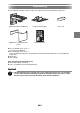
Unpacking As you unpack the product, check to make sure that all of the items listed below are present. Wall anchor plate and bracket Projector anchor plate Upper/lower wall anchor plate covers Positioning sheet Arm cover z M4 × 10 Double sems screw – 4 (For projector installation) z M5 × 10 Double sems screw – 3 (Two for installing the projector anchor plate to the main wall mount bracket, one for installing the safety wire.
Installing the Wall Mount Bracket Precautions During Installation z Be sure to follow the procedures in this manual to ensure that installation work is performed correctly. Make sure that screws, metal parts, and all other components are all installed securely. z Check to make sure that the wall where the bracket is to be installed can support the weight of the bracket, and arrange for installation plans and installation work.
Installing the Wall Mount Bracket 2. Install the wall anchor plate. 1. Referring to “Screen Size and Wall Anchor Plate Mounting Dimension Diagram” (page EN-8), determine the installation position. 2. Referring to “Positioning the Installation Holes of the Wall Anchor Plate” (page EN-9), drill holes in the wall. 3. Use the anchor bolts to install the wall anchor plate.
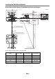
Installing the Wall Mount Bracket Screen Size and Wall Anchor Plate Mounting Dimension Diagram 413 308 206 Unit : mm L H1 84 H2 141 28.6 333 Center of wall anchor plate 52.5 Screen Size Center of projection screen Screen Thickness [Screen Settings] Aspect Ratio : Full (1280 × 800) Screen Size (inch) L (mm / inch) H1 (mm / inch) H2 (mm / inch) 50 60 / 2.4 200 / 7.9 325 / 12.8 60 128 / 5 227 / 8.9 352 / 13.9 80 267 / 10.5 281 / 11.1 406 / 16 100 404 / 15.9 335 / 13.2 460 / 18.
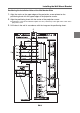
Installing the Wall Mount Bracket Positioning the Installation Holes of the Wall Anchor Plate 1. Align the marks on the upper edges of the projection screen printed on the positioning sheet with the upper edges of the projection screen. 2. Align the positioning sheet with the center of the projection screen. z Position the center of the wall anchor plate 52.5 mm (2.07 inches) to the right of the center of the projection screen. 3.
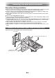
Installing the Wall Mount Bracket 3. Attach the bracket unit to the wall anchor plate. 1. Remove the screw and then remove the cable guide bracket. 2. Pass the cable through the main bracket. 3. Return the cable guide bracket to its original position and secure it with the screw. Pass the cable through the arm. Screw Secure the cable with the cable guide brackets. Important! z Route the cable as shown above, taking care not to damage it. z Do not try to force the cable through the arm. 4.
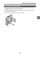
Installing the Wall Mount Bracket 4. Install the projector. 1. Use the four M4 × 10 screws (included) to attach the projector anchor plate to the projector unit. 2. Slide the projector onto the bracket unit so it hooks onto the shoulder bolt. 3. Insert the two M5 × 10 fixing screws (included) and tighten them.
Installing the Wall Mount Bracket 5. Attach the safety wire. 1. Hook the wire on the projector’s hook as shown in the illustration. 2. Use an M5 × 10 double sems screw to secure the wire to the main bracket. Screw 6. Connect cables. 1. Referring to the projectors user documentation, connect the cables that you routed in step 3-1 of the procedure above.
Adjusting the Position, Elevation, and Angle Important! + z Firmly support the projector from below whenever adjusting the elevation and/or angle. After adjustment is complete, re-tighten all of the screws. Installation by non-specialists creates the risk of the bracket and projector falling down and other problems. Precautions when Adjusting the Projection Screen z Project onto a board type screen or other suitable flat, even surface.
Adjusting the Position, Elevation, and Angle Make adjustments so the projected image is positioned properly on the screen. z The procedures in this section are explained assuming that you are starting from the projectors initial factory default settings. Note required adjustments will be different if you have changed the projector’s keystone correction or other settings. z For information about projector operation, see the projector user’s guide. 1. Turn on the projector and project the blue screen. 2.
Adjusting the Position, Elevation, and Angle 1 Projection area size adjustment Adjustment range: 50 to 110 inches Loosen the adjustment screw, adjust the projected image size, and then re-tighten the adjustment screw. Adjusting screw: If the screen you are using is larger than 60 inches, loosen this screw and pull out the large telescoping arm section in addition to the small arm.
Adjusting the Position, Elevation, and Angle 3 Product vertical angle adjustment Adjustment range: ±3° After loosening the fixing screw and making adjustments with the adjusting knob, tighten the fixing screw securely. fixing screw Adjusting knob Center position: Left and right holes equally visible 4 Product horizontal angle adjustment Adjustment range: ±5° After loosening the fixing screw and making adjustments with the adjusting knob, tighten the fixing screw securely.
Adjusting the Position, Elevation, and Angle 5 Projection area horizontal position adjustment Adjustment range: ±30mm (1.2 inches) After loosening the fixing screw and making adjustments with the adjusting knob, tighten the fixing screw securely. Fixing screw Adjusting knob Center position: The small hole under fixing screw slot indicates the center position. 6 Projection area rotation angle adjustment Adjustment range: ±5° 1. Loosen the positioning screw. 2.
Attaching the Covers z After adjustments 1 through 6 are complete, tighten the screw with spring washer (fixing screw) securely. Screw with spring washer (fixing screw) Attaching the Covers Attach the upper and lower wall anchor plate covers and the arm cover. Upper wall anchor plate cover Arm cover Lower wall anchor plate cover Attaching the Lower Wall Anchor Plate Cover 1. Align the four hooks on the back of the cover with the four holes of the bracket. 2.
Periodic Inspection Perform the inspections described below once a year. 1. Check to make sure that none of the wall mount bracket screws are loose. 2. Check to make sure that the wall mount bracket, the covers, the projector, and other items are not scratched, damaged, etc. Contact Whenever you have any questions or concerns, contact your CASIO retailer. Product Specifications Approximate Dimensions: 200 (W) × 410 (D) × 270 (H) mm (7.9" × 16.1" × 10.
Printed in Japan Imprimé au Japon MA1407-B