IN Wall Mount Bracket YM-81 English User’s Guide
Wall Mount Bracket YM-81 User’s Guide Be sure to keep all user documentation handy for future reference. To obtain the latest version of this manual, visit the website at the URL below. https://world.casio.com/manual/projector/ Contents Safety Precautions ....................................IN-2 Attaching the Covers .............................. IN-27 Operating Precautions ..............................IN-3 Periodic Inspection ................................. IN-29 Unpacking .....................
Safety Precautions Thank you for selecting this CASIO product. Be sure to read these “Safety Precautions” before trying to use it. After reading this User’s Guide, keep it in a safe place for future reference. About safety symbols Various symbols are used in this User’s Guide and on the product itself to ensure safe use, and to protect you and others against the risk of injury and against material damage. The meaning of each of the symbols is explained below.
Operating Precautions * Warning This product does not have rotary angle adjustment. After adjusting the elevation and angle, never rotate the projector while the screws are tightened. After installation is complete, leave all elevation and angle adjustments up to qualified specialists. Adjustment by non-specialists creates the risk of the bracket and projector falling down. After the Projector System is installed, never loosen any of its bolts, screws, or nuts.
Operating Precautions Concrete - When mounting on a concrete wall, use appropriate components (M10 nuts, bolts, etc.) to support the weight of the projector and bracket, and to prevent lateral sway. Adjustment by non-specialists creates the risk of the bracket and projector falling down. CASIO COMPUTER CO., LTD. shall be held in no way liable for any losses due to the bracket and/or projector falling down due to the use of installation components of insufficient strength.
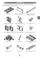
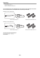
Unpacking As you unpack the product, check to make sure that all of the items listed below are present. Values in brackets (< >) indicate quantities.
Unpacking Positioning sheet <1> User’s Guide (This Manual) <1> The wall mount bracket comes with either of the two safety wire types and lengths shown below. The size of the hex head screws depends on the safety wire type and length.
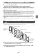
Installing the Wall Mount Bracket Precautions During Installation Be sure to follow the procedures in this manual to ensure that installation work is performed correctly. Make sure that screws, metal parts, and all other components are all installed securely. Check to make sure that the wall where the bracket is to be installed can support the weight of the bracket, and arrange for installation plans and installation work.
Installing the Wall Mount Bracket 4. Use the anchor bolts to attach the anchor plates to the wall. Securely attach the anchor plates to the wall using at least eight anchor bolts: at least four for the middle wall anchor plate, and at least two each for the left and right wall anchor plate. Important! With a projector installed, this product weighs approximately 13 kilograms (28.7 lbs). When attaching this product to a wall, carefully consider pull out strength and installation strength.
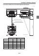
Installing the Wall Mount Bracket Screen Size and Wall Anchor Plate Mounting Dimension Diagram Unit : mm Ceiling 502.8 (233) 161.2 H 69 43.8 141 126.1 205 205 76.4 MAX.722.1 - MIN.501.1 200 333 L Center of wall anchor plate Center of projection screen 62.7 Screen Size 413 Screen Thickness WXGA Screen Size (m/inches) L (mm/inch) XGA H (mm/inch) L (mm/inch) H (mm/inch) 1.27 / 50 -/- -/- 121 / 4.8 253 / 10.0 1.52 / 60 128 / 5.0 240 / 9.4 202 / 8.0 288 / 11.3 1.
Installing the Wall Mount Bracket Positioning the Installation Holes of the Wall Anchor Plates 1. Align the marks on the upper edges of the projection screen printed on the positioning sheet with the upper edges of the projection screen. The scales on either side of the positioning sheet indicate millimeter units. 2. Align the positioning sheet with the center of the projection screen. Position the center of the wall anchor plate 62.7 mm (2.
Installing the Wall Mount Bracket 2. Install the adjuster unit onto the arm unit. 1. Remove the bracket from the adjuster unit. The adjuster unit is packed with the bracket attached. Remove the bracket as shown in the illustration. Adjuster unit Bracket (with projector anchor plate) 2. Loosen the arm unit hex head screw indicated in the illustration and then pull out the inner arm. Next, orient the adjuster unit as shown in the illustration and insert it into the inner arm.
Installing the Wall Mount Bracket Note that the attachment procedure you should use depends on whether the eyelet of the included safety wire is straight or angled. Check the eyelet on your safety wire to determine which installation procedure you should use. To connect a straight eyelet safety wire 3. Secure the adjuster unit to the inner arm using four M4×8mm hex head screws.
Installing the Wall Mount Bracket To connect an angled eyelet safety wire 3. Secure the adjuster unit to the inner arm using three M4×10mm hex head screws. Important! As shown in the illustrations below, you need to determine the adjuster unit installation location on the inner arm in accordance with your projector’s resolution (WXGA or XGA) and the desired projection size.
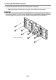
Installing the Wall Mount Bracket 3. Install the arm unit on the wall anchor plates. 1. Insert the M10×152mm arm vertical adjustment screw into the hole of the arm unit. Align the red mark of the adjustment screw as shown in the illustration. Arm unit Arm vertical adjustment screw Red mark Groove 2. Temporarily hook the arm unit onto the two screws of the middle wall anchor plate. You do not need to tighten the screws.
Installing the Wall Mount Bracket 3. Insert the two M10×194mm arm screws into the holes in the middle wall anchor plate, and then tighten the screws with the provided hex wrench. 4. Secure the two arm screw covers with the M4×8mm hex head screws or M4×10mm hex head screws. Arm screws Arm screw covers M4×8mm hex head screws or M4×10mm hex head screws 5.
Installing the Wall Mount Bracket 4. Install the projector. 1. Attach anchor plate to the projector using four M4×8mm hex head screws or M4×10mm hex head screws. M4×8mm hex head screws or M4×10mm hex head screws Projector anchor plate Bracket Projector 2. Slide the bracket into the adjuster unit and secure it in place using the screws specified in the illustration.
Installing the Wall Mount Bracket 5. Attach the safety wire. Note that the attachment procedure you should use depends on whether the eyelet of the included safety wire is straight or angled. Check the eyelet on your safety wire to determine which installation procedure you should use. To connect a straight eyelet safety wire 1. Pass the safety wire through the outer arm of the arm unit and then loop it as shown in the illustration. Arm unit 2.
Installing the Wall Mount Bracket To connect an angled eyelet safety wire 1. Pass the safety wire behind the anti-theft bar and then loop it as shown in the illustration. 2. Route the cable along the outside of the arm unit, and use an M4×10mm hex head screw to secure the wire along with the adjuster unit to the screw hole at the location on the top of the arm unit as shown in the illustration.
Installing the Wall Mount Bracket 6. Connect the cables to the projector. 1. Pass the cables to be connected to the projector through the arm hole as shown in the illustration. If you want to run cables along the top of the arm instead of the bottom, install the left and right wall anchor plate covers (page IN-28) and then run the cables through the openings in the top of the covers. 2. Refer to the projector’s User’s Guide for information about how to connect power and external equipment cables.
Adjusting the Position, Elevation, and Angle Important! + Firmly support the projector from below whenever adjusting the elevation and/or angle. After adjustment is complete, re-tighten all of the screws. Installation by non-specialists creates the risk of the bracket and projector falling down and other problems. Unless specifically instructed otherwise, adjustment should be performed with the projector in its initial factory default state.
Adjusting the Position, Elevation, and Angle 1. Start adjustment. 1. Turn on the projector. If the projector is in its initial factory default setup, it will project a blue screen (when there is no input signal). Projection of a test pattern is recommended, if possible. For more information, refer to the projector’s User’s Guide. Important! Take care to keep your hands away from the area around the projector’s exhaust vents while the projector is turned on.
Adjusting the Position, Elevation, and Angle 2. Adjust the projected image. While monitoring the projected image, make the adjustments listed below.
Adjusting the Position, Elevation, and Angle Projected image size adjustment Adjustment range: WXGA: 1.52m (60") to 2.79m (110") XGA: 1.27m (50") to 2.29m (90") 1. Slide the arm forward or back to adjust the size of the projected image. While checking the applicable scale on the side of the arm unit, slide the arm forward or back. WXGA: 2.03m (80") or larger projection size XGA: 1.78m (70") or larger projection size Image Size Scale Upper: WXGA (red) Lower: XGA (green) WXGA: 1.
Adjusting the Position, Elevation, and Angle Projected image vertical position adjustment Adjustment range: ±35 mm (1.4 inches) Use the included hex wrench to rotate the arm vertical adjustment screw. When viewed from the bottom of the middle wall anchor plate, rotating the screw clockwise lowers the arm position, while counterclockwise rotation raises it. Middle wall anchor plate Arm vertical adjustment screw Projected image horizontal position adjustment Adjustment range: ±50 mm (2.
Adjusting the Position, Elevation, and Angle Projected image horizontal tilt adjustment Adjustment range: ±5° Rotate the red adjustment knob. Projected image vertical keystoning adjustment Adjustment range: ±5° Rotate the blue adjustment knob. Projected image horizontal keystoning adjustment Adjustment range: ±5° Rotate the green adjustment knob.
Adjusting the Position, Elevation, and Angle 3. Complete the adjustment procedure. Securely tighten the five screws shown below. Use the included hex wrench to tighten Screw (4).
Attaching the Covers 1. Attach the arm cover to the end of the arm unit. Press the arm cover until the tabs on its left and right sides engage with the holes on either side of the inner arm. Inner arm Arm cover 2. Attach the cable cover to the projector. For information about attaching the cable cover to the projector, refer to the projector’s User’s Guide. 3. Secure the middle wall anchor plate cover to the bottom of the arm with two M4×8mm hex head screws or M4×10mm hex head screws.
Attaching the Covers 4. Attach the left and right wall anchor plate covers. As shown in the illustration, attach the right cover first and then the left cover. Left wall anchor plate cover Right wall anchor plate cover 5. Install an M4×20mm screw into the screw holes in the bottom of the left and right wall anchor plate covers and tighten it to secure the covers.
Periodic Inspection Perform the inspections described below once a year. 1. Check to make sure that none of the wall mount bracket screws are loose. 2. Check to make sure that the wall mount bracket, the covers, the projector, and other items are not scratched, damaged, etc. Contact Whenever you have any questions or concerns, contact your CASIO retailer. Product Specifications Approximate Dimensions: 500 (W) × 470 (D) × 190 (H) mm (19.7" x 18.5" x 7.
MA2002-A D580MAN1-IN