
Castle X Series Drivers Ed Guide


3
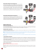
Brushed Motor Wiring, Reversing (Figure 3)
Use this mode if you wish to use reverse. Make sure you change the Motor
Type setting to “Brushed Reversing” in the ESC before using a brushed motor.
Use only the red and black motor wires from the ESC, or the outside bullet
connectors on the ESC. In most applications, the red wire from the ESC will
connect to the red wire (or positive + side hood) of the motor, and the black
wire to the black wire (or negative - side hood) of the motor. The white
wire from the ESC (or middle bullet connector on the ESC) is not used. After
calibration (See “How to Calibrate the ESC” below), you may need to swap
the two motor wires to get the wheels to spin in the right direction.
Brushed Motor Wiring, High Power (Figure 4)
Using High Power Brushed Motor mode will allow for the use of lower turn
count brushed motors, and forward only operation. Make sure you change
the Motor type setting to “Brushed High Power” in the ESC before using a
brushed motor. Connect all three of the ESC motor wires to the black wire (or
negative (-) hood) of the motor. Connect the red wire (or positive (+) hood) of
the motor to the positive (red) wire at the ESC’s battery plug.
RADIO CONNECTION
RX Wire (Orange/Red/Brown)
Your Castle ESC RX wire plugs into the throttle channel of your receiver. This is usually channel 2. Your Castle ESC provides power
to the receiver and the steering servo. No separate receiver battery is needed to power the radio system. Some servos can draw
more current than the on-board BEC can handle and will require an external BEC or receiver pack.
AUX Wire (White Signal Wire)
The Auxiliary or “AUX” wire allows you to adjust a setting “on-the fly” using an auxiliary channel on your receiver. The AUX wire
function is programmable via Castle Link.
Castle ESC receiver plugs are designed to work with any current receiver, but you will need to make sure the polarity is correct
when connected to the receiver. The ESC signal wire is orange or white, the positive wire is red, and the negative wire is brown.
Check your receiver documentation for correct connection polarity if it’s not marked.
Most receivers use negative (brown) towards the outside of the case and signal (orange/white) towards the channel markings
on the case.
Castle ESC/Radio Calibration
Individual transmitter signals for neutral, full throttle, and full brake vary. You must calibrate your Castle ESC so that it will operate
effectively with your transmitter. Anytime the ESC is powered up with a new transmitter or with different throttle channel
settings, it will need to be calibrated to the transmitter’s throttle settings. The ESC may also need to be calibrated after updating
to new software via Castle Link.
If you are using a Futaba-made transmitter, you will need to set the transmitter’s throttle channel direction to the REVERSE (Rev)
position. This is either an external micro switch on the transmitter or an option available within the computer programming of the
transmitter. Please start by zeroing out any throttle trim that you may have set in your transmitter.
How To Calibrate The ESC
Safety First! Remove the pinion prior to calibration.
Step 1: Start with the transmitter ON, the battery disconnected, and the ESC switch in the OFF position (if your ESC has a switch).
Step 2: Plug a battery into the ESC. If your ESC does not have a switch, hold full throttle on your transmitter before plugging in
the battery.
Figure 3
Figure 4