CASTLE INC Owners Manual AT-8
CASTLE, INC AT‐8 OWNERS MANUAL V2.
Table of Contents 1 INTRODUCTION.............................................................................................................................4 2 MACHINE SAFETY.........................................................................................................................5 3 4 2.1 KEY FEATURES ..........................................................................................................................5 2.2 INVENTORY ..............................................
1 Introduction Thank you for making the Castle AT-8 the latest addition to your shop. Since 1985 our goal has been to manufacture and develop machines that make cabinetmaking and casework easier, faster and more profitable for the woodworker. This machine represents our commitment to your productivity. Castle machines are made in Petaluma, California and are manufactured to the highest standards using local vendors wherever possible.
2 Machine Safety NOTICE: The Castle Frame Assembly Table was designed with operator safety as a priority. This machine was carefully prepared for shipment at our factory. Upon receipt of the machine, inspect for shipping damage. Report any damage IMMEDIATELY to the freight company, your Castle dealer and to Castle, Inc. DO NOT attempt to operate the machine if you observe any physical damage. Contact Castle, Inc. at 800.282.8338 for instructions. 2.
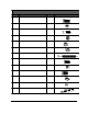
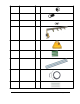
CASTLE AT-8 ASSEMBLY TABLE HARDWARE PACK Part # Part Description Qty F51878 5/16-18 X 7/8 HHCS (Frame Assembly) 25 F51628 5/16-18 Hex Nuts (Frame Assembly) 25 F44134 ¼-20 X 1-3/4 FHCS (Fence Installation) 12 F01422 ¼-20 Kep Nut (Fence Installation) (Arm Stop Bolts) 12 2 N00345 5/16 Large Aluminum Spacer (Fence Installation) 8 N00346 5/16 Small Aluminum Spacer (Fence Installation) 4 F10212 #10 x 2-1/2” Phillips Pan Head Sheet Metal Screw (Worktop Installation) 30 F14585 ¼-20 x 5/8 HH
F38168 3/8-16 Hex Nut 12 F38161 3/8-16 x 1 HHCS 8 F03876 3/1 USS Flat Washer 12 C08008 AT Frame Table Arm Assembly 1 C08009 AT Arm Top Bracket Assembly 1 G08516 AT Leg Braces 4 O08474 AT-8 Side & Bottom Fence 3 C08000 S12043 P14170 Sioux Air Gun Hose Spiral Wrap – 8” ¼ OD Black Tube – 16” 1 1 1 G08512 G08513 AT-8 Joining Bracket AT-8 Splice w/Welded Bolts 2 1 CASTLE, INC AT‐8 OWNERS MANUAL V2.
2.3 Machine Requirements Your Castle AT-8 Face Frame Assembly Table requires a minimum of 85 PSI air not to exceed 150 PSI. Supply Line should be a minimum of ¼” line. Install an air filter trap to reduce the potential for foreign particles and water from your air supply prior to entry into the machine. The filter should be mounted to the wall where your supply comes from and SHOULD NOT be mounted to your machine. 2.
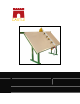
3 Setting Up Your AT-8 Your Castle AT-8 Assembly Table is shipped knocked-down, with the legs bolted to a pallet and the frame and top inside. 3.1 Frame Assembly 1. Remove the clamp arm from the pallet by cutting the two zip ties. 2. Unbolt the legs on the narrow side of the pallet and open them to an almost parallel position. 3. Remove the packing envelope.
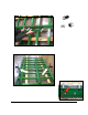
9. Position all three joining plates [G08513 & G08512] and bolt loosely in position using 3/8-16 x 1” bolts [F38161], 3/8 Nuts [F38168] and 3/8 washers [F03876]. 10. Using the pictures as guide, clamp the joints at the top and bottom of the frame. Make these joints as flush as possible. Keep in mind that the bearings for the clamp arms are going to roll along this joint. 11. Tighten top and bottom joining plates first, then tighten all the plates.
12. Attach the legs and leg braces 13. To attach each leg you will need: a. (2) leg braces [G08516], b. (6) 5/16-18 x 7/8” hex head cap screws [F51878] and c. (6) 5/16-18 hex nuts [F51628]. 14. Have someone hold the leg while you fasten it to the frame. The flat part of the angle iron should face the inside of the machine. 15. Attach the (2) leg support bracket using bolts supplied. Repeat this process for the other side. 16.
3.2 Fence Installation 1. Attach the fences using the ¼-20 Flat Head bolts [F44134], aluminum spacers [N00345 and N00346] and the ¼-20 Kep Nuts [F01422]. The side fence uses the small spacers and the bottom fence uses the larger spacers. Caution: When fastening the fences be sure to only tighten one bolt on each fence at the bottom left corner of the frame. You will tighten the rest later. CASTLE, INC AT‐8 OWNERS MANUAL V2.
3.3 Worktop Installation 1. Place the table top onto the frame, make sure the top is sitting as far left as it will go and flat on the bottom. 2. Starting with the top swing the left top onto the spline. 3. Push together tightly from right side CASTLE, INC AT‐8 OWNERS MANUAL V2.
4. Install draw bolts [F14312]. 5. Using the (30) #10 X 2-1/2” pan Phillips sheet metal screws [F10212] fasten the table down through the rear of the frame. 6. Place a sheet of plywood measuring AT LEAST 4’ x 8’ on the table, and rest it on the bottom fence. 7. Push up on the end of the fence opposite the end with the tight bolts until the fence is flush with the wood. Now tighten all of the bolts for the fences. CASTLE, INC AT‐8 OWNERS MANUAL V2.
3.4 Arm Installation 1. Attach the arm bracket to the aluminum beam using the 5/16-18x5/8 HHCS bolts [F51638] and 5/16-18 T-nuts [F51698] supplied. 2. Position the clamp arm onto the frame from the right side. 3. The length of the arm may need to be adjusted at the upper arm bracket. 4. Square the arm vertically by loosening 3 of the 4 bolts and drawing the arm parallel with the left fence. 5. Slide the top bracket to achieve proper lower bearing adjustment. 6.
3.5 Connecting Air 1. The air regulator on the upper bracket is rotated 180 degrees for its protection in shipping. 2. To rotate the regulator and gauge, loosen the nut located on the outside of the bracket (shown) and rotate. 3. Use the ¼” OD X .17 ID x 16” Black Tube [P14170] included to connect air from the regulator to the push-in fitting at the top of the arm. 4. Connect air to your Assembly Table at the Main Air In port on the regulator.
5. To set the Air Pressure, pull the yellow knob on the regulator out and turn the knob until the pressure measures 85 PSI on the gauge. CASTLE, INC AT‐8 OWNERS MANUAL V2.
4 Operating Instructions Warning: Always wear eye protection when operating pneumatic equipment. 4.1 Cylinder Actuation To operate the clamp cylinder locate the black lever with the rubber stopper. Moving this lever back and forth will clamp and release the cylinder. Your Assembly Table beam arm is fitted with (5) ports for air fittings and can accommodate an optional fifth clamp cylinder. CASTLE, INC AT‐8 OWNERS MANUAL V2.
4.2 Screw Bowl Holder The Screw Bowl is held in place by the red lever on the Clamp Arm Bottom Bracket. Pull the lever down to release the bowl and push it up to hold the bowl in place. 4.3 Optional Screw Gun Airline Your Castle Assembly Table comes with a 3/8” AT Gun Hose Assembly [C08000]. To attach the Air Screw Gun (optional) remove the red plug from the regulator and connect the AT Air Gun Hose Assembly. Next, thread the hose through the aluminum arm.
5 Maintenance Note: Contact a Castle, Inc service technician for proper service information. It is suggested that the table top be periodically cleaned of excess glue and/or dust. The Poly Foot Pads are subject to wear over time and should be replaced. If you notice a considerable slow down in the speed of the cylinder actuation, the cylinder may need to be rebuilt using the AT Cylinder Rebuild Kits (Part #K08004).
6 Trouble Shooting Guide 6.1 Adjusting the Arm Bearings Your Assembly Table Arm rides on two sets of bearings; one at the bottom bracket and one at the upper bracket. If the arm becomes loose or rides on the beam roughly, these bearing sets may need to be tightened. This procedure is performed best with two people. 1. Loosen the four bolts in the top bracket that hold the arm in place while someone holds the bottom bracket firmly in place against the table. UPPER BRACKET ARM BOLTS BEARING NUTS 2.
6. If the bearings were loose, the tightening procedure could change the arm positioning. Test the positioning of the arm by rolling it along the beam. It should roll smoothly the whole way and be parallel to the tabletop. 6.2 Aligning the Arm When your Castle Assembly Table is set up or reassembled after relocation, the arm must be aligned to ensure proper operation. Note: This procedure requires two people. 1.
6.3 Tightening Bracket Bolts The bottom bracket is held to the aluminium clamp bar by two bolts. If either of these bolts is loose or slightly tweaked out of shape, the pneumatic seal won’t hold. It is important that these bolts be tight. LOWER BRACKET BOLT BRACKET ARM SEAL Warning: Bottom Bracket bolts are tapped directly into the aluminium. If they are overtightened they may strip out the arm. 1. Check that the bolts on the bottom bracket are tight. 2.
6.5 Tightening the PEM Nut Note: This procedure requires two people to remove the arm assembly from the table. The cylinder lever is held against the body of the cylinder with a PEM nut. If you notice that the cylinder lever has come loose or that your clamp cylinder does not hold pressure the PEM nut may have come loose. This nut can be tightened by first removing the cylinder and then tightening up the nut. 1. Turn off the air and remove the airline for the cylinder with the loose lever.
1. Turn off the air and remove the airline for the cylinder to be rebuilt. The line is connected to the cylinder by a push-in fitting. Push the outer ring in as you pull the airline out. 2. Loosen the tension screw on the side of the Cylinder Channel. 3. Remove the (4) Wear Strip screws on each side of the Cylinder Channel and remove the complete assembly from the arm. 4. With the cylinder off the arm remove the Snap Ring (#2) on Appendix A 5. Remove the piston (#1). 6.
7 Appendix A – Clamp Cylinder Detail 5 2 13 14 Fig 1 CASTLE, INC AT‐8 OWNERS MANUAL V2.
Item # Part # 1 Part Description Qty Cylinder Piston Assembly 1 2 D15800 Internal Retaining Ring, 1-5/8 1 3 G08006 AT Cylinder Sleeve 1 4 F10377 10-32 x 7/8 PPMS – Machine Screw 1 5 M08615 AT Stainless Steel Washer 1 6 G00051 AT Reinforced Neoprene Rubber Gasket 1 7 G08001 AT Air Cylinder Channel 1 8 F80122 #8 x ½” Phillip Pan Sheet Metal Screw 4 9 F10338 10-32 x 3/8” Phillip Pan Machine Screw 1 10 F32012 AT Pem Stand-Off 1 11 F10000 #10 SAE Flat Washer 1 12 G
8 Appendix B – Cylinder Piston Detail Fig 2 CASTLE, INC AT‐8 OWNERS MANUAL V2.
Item # Part # 1 N70118 Poly Foot Pad, 1 x 1/8 1 2 F14204 ¼-20 x 4 Phillips Flat head Machine Screw 1 3 N08005 AT Cylinder Foot 1 4 N08011 AT Air Cylinder Ring 1 5 H11135 AT Cylinder Return Spring 1 6 O08075 AT Cylinder Piston Rod 1 7 N08010 AT Air Cylinder Piston 1 8 H32200 Buna-N O-Ring – 322 1 CASTLE, INC Part Description AT‐8 OWNERS MANUAL V2.
9 Appendix C - Assembly Table Accessories Visit our web store to purchase service parts, options and accessories for your Castle Assembly Table. We offer Sioux Air Drills, additional Clamp Cylinder Assemblies and Open Back Conversion kits among other items. http://castleusa.com/webstore/ AT Clamp Cylinder Assembly PART # C08002 AT-OB CONVERSION KIT PART # K05001 Sioux Pneumatic Screw Gun PART # T22607 CASTLE, INC AT‐8 OWNERS MANUAL V2.