Screw Pocket Machine Model TSM-21 Operator Manual Read and understand this manual before using machine Castle, Inc. 1364 N. McDowell Blvd, Ste 1 Petaluma, CA 94954 (800)282-8338 U.S. Patent No.
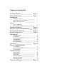
Table of Contents Customer Promise_______________ Page 1 Safety Notification_______________ Page 1 Introduction Definition of Terms_______________________ Operating Features and Controls_____________ Manual Contents Notice___________________ 2 3 5 Safety Types of Warnings_______________________ General Safety Rules_____________________ 6 6 Machine Inventory_______________ Page 8 Electrical and Air Requirements____ Page 8 Set Up and Installation____________ Page 9 Initial Configuration ______________ Pag
Customer Promise In a perfect world, there would be no need for Technical Support and Service. At Castle, Inc. we recognize that the world is not perfect (yet), so please call Castle Technical Support if you encounter a problem with your Castle machine. 1 (800) 282- 8338 The jog and jostle of shipping and handling can undo even the most strict quality measures. Many difficulties that may occur in a new machine can be identified with a simple test or resolved with a simple adjustment right over the phone.
Introduction Fortify Your Shop Thank you for making the Castle TSM-21 Screw Pocket Machine the latest addition to your shop. Since 1985 our goal is to manufacture and develop machines that make cabinetmaking and casework easier, faster, and more profitable for the woodworker. This machine represents our patented screw pocket cutting technology. Castle machines are made in Petaluma, California and are manufactured to the highest standards using local vendors wherever possible.
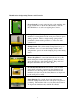
Identification of Operating Features and Controls 1. Power Switch: Located on the left side of the machine, this toggle switch turns on the Pocket Router Motor and the Pilot Drill Motor as well as energizing the Controls. 2. Clamp Cylinder: The large cylinder on the top of the machine is a clamp that holds the work piece safely in place during operation. This is a single-acting, spring-return, pneumatic cylinder with a padded foot on the end of the cylinder rod. 3.
7. Safety Switch: This magnetic proximity switch is mounted inside, near the top of the TSM-21. It is activated when the Safety Buttons are depressed by the work piece. 8. Motor Carriage: The Motor Carriage is the yellow, pivoting A-frame structure inside the machine. Both the Router Motor and the Drill Motor are mounted to this carriage. The forward and back carriage motion during the machine cycle is provided by the Drive Cylinder. 9.
Manual Contents Notice This manual is not totally comprehensive. It does not and cannot convey every possible safety and operational problem which may arise while using this machine. The manual will cover many of the basic and specific safety procedures needed in a shop environment. All federal and state laws and any regulations having jurisdiction covering the safety requirements for use of this machine take precedence over the statements in this manual.
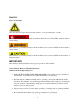
Safety Types of Warnings Obey all safety messages that follow this symbol to avoid possible injury or death. This indicates an imminently hazardous situation which, if not avoided, WILL result in death or serious injury. This indicates a potentially hazardous situation which, if not avoided, COULD result in death or serious injury. This indicates a potentially hazardous situation which, if not avoided, COULD result in minor or moderate injury.
• Keep all body parts away from the moving parts of this machine whether it is in operation or at rest. • Do not place hands or fingers between the work piece and the clamp or near the cutters at any time. Always use a securing device when undertaking close work. • Do not wear gloves or loose clothing (such as sweaters, jackets, or jewelry) when operating or standing near an operating machine. • Keep two hands on the work piece when initiating a pocket cycle on this machine.
Inventory With your Castle machine you should have received the following: Warranty Card (Please fill out & mail to Castle, Inc.
Set-up / Installation Always use eye protection when operating power equipment. Your Castle TSM-21 Pocket Cutter was set up and tested for proper operation at the factory. It is normal to find a small amount of sawdust in the TSM-21 from this process. Verify that the Power Switch is turned off. Remove the Power Cord and Foot Pedal from inside the machine. Remove the swivel elbow from the black urethane hose by pushing the floating ring toward the elbow and pulling the hose at the same time.
The Motor Carriage on your machine is secured against movement during shipping. Open the rear door and look toward the top of the machine just left of center for the black Router Stop Plate. Cut the zip tie that secures the yellow Motor Carriage to the Router Stop Plate and let the carriage move forward to its neutral position. Inspect the TKnobs and the U-Bolt on the carriage (Figure 3), making sure that the motors are secure and tight.
Initial Configuration Now that the machine is connected to a power source and air supply, it is suggested that you test the machine’s controls for proper function. Read the Operator Manual carefully before operating. Make sure that you have followed all assembly and installation instructions correctly. Make sure that you are familiar with the functions described in the rest of the manual as well. Failure to follow this warning may result in serious injuries to persons and property.
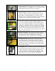
Inspect the pocket. If the drilled hole is off center (Figure 6), it can be centered using the adjusting nut on the Pilot Hole Adjustment Bolt just below the drill motor. (Figure 7) Figure 6 Figure 7 Tightening the nut moves the drill tip left relative to the operator. Adjust accordingly. The Router Feed rate can be adjusted by using the flow control knob next to the air supply port (Refer to the Adjustment chapter on page 14).
Adjustments Router Feed Rate Adjustment Figure 8 The Router Feed Rate Adjustment knob is located just under the air inlet port on the left side of the machine. (Figure 8) The adjustment knob only affects the cutting stroke of the pocket router. Turning the knob clockwise selects a slower Feed Rate. Turning the knob counter-clockwise selects a faster Feed Rate.
Pocket Web Adjustment The offset distance from the end of the pocket to the edge of the work piece is called the “Web.” (Figure 9) It has been factory set at approximately 7/8” to accommodate 1 ½” screws. Figure 9 If you are using 1¼” screws you may choose to shorten the Web to 5/8”. IMPORTANT The minimum recommended Web under any circumstance is 5/8”. The Web is adjusted by shortening or lengthening the travel of the router’s cutting stroke.
Pocket Depth Adjustment The router bit for cutting the pocket is inserted into the router collet at the factory for a distance of 1 5/16” from the tip of the bit to the collet. This setting cuts at an optimal depth of approximately 3/8” for material between 5/8” and 7/8” thickness. To cut a shallower pocket (in ½” material for example): Place a shim with a known thickness on the work top and place your work piece over it.
Drill Feed Rate Adjustment The stroke speed with which the machine drills the pilot hole (and clamps the work piece) is solely a function of the air pressure set at the internal Pressure Regulator. There is no separate adjustment knob. IMPORTANT If the Drill Feed Rate is so fast that the machine shakes violently during the Pocket Cycle or if the Drill Feed Rate is so slow that the Pocket Cycle is significantly longer than two seconds, then it may be necessary to adjust the Pressure Regulator .
Pilot Drill Depth Adjustment The Pilot Drill operation works best when the drill depth is adjusted so that the drill bit just barely breaks into the pocket. If the drill bit extends farther than necessary, it can cause shorter bit life and over-size holes. The drill bit is set at the factory for a length of approximately 1 13/16” from tip to drill motor collet (this is a suitable distance for the factory default 7/8” Web).
Pilot Drill Height Adjustment The position of the Pilot Hole can be raised or lowered slightly to accommodate various thickness in work pieces or various pocket depths. On the sides of the machine case, secure the Carriage Centering Screw with a 1/8” allen wrench. Loosen - but do not remove - the nylon lock nuts securing the set screw of the Motor Carriage to the machine case.
Operation Read the Operator Manual carefully before operating. Make sure that you are familiar with the functions described in the rest of the manual as well. Failure to follow this warning may result in serious injuries to persons and property. IMPORTANT Always use eye protection when operating power equipment. With the Power Switch turned off, check to see that the carriage moves freely by hand and returns to the neutral position (Figure 17).
Turn the Power Switch on (Figure 19). Figure 19 Place the work piece to be pocketed on the Work Top. Slide it under the Clamp Guard and firmly push it against the face plate of the machine to press the Safety Buttons. (Figure 20) Figure 20 Be sure to keep your hands clear of the clamp, then press and release the Foot Pedal to activate the cutting cycle. The pocket will be cut at the point directly under the center of the Clamp Cylinder.
Service and Maintenance Tool Changes DO NOT ATTEMPT TO CHANGE TOOLING WITH COMPRESSED AIR OR POWER SUPPLIED TO THE MACHINE!! To change the Pocket Router Bit or the Pilot Drill Bit you will need to remove the respective motor from the carriage. You do not need to remove the Work Top to change the bits. Pocket Router Bit Open the rear door and unplug the router motor. Locate the black T-Knob to the right of the drill motor at the top of the carriage.
Pilot Drill Bit Open the rear door and unplug the drill motor. Locate the black T-Knob to the left of the drill motor at the top of the carriage (Figure 23). The black T-Knob is threaded onto a set screw that secures the Drill Motor. Unscrew and remove the T-knob. Slide the motor slightly to the right until the set screw clears the mounting hole, then lift the motor out through the rear door and change the tooling.
General Machine Maintenance The model TSM-21 requires some maintenance. To ensure productivity and longevity of your Castle Pocket Cutter, it is essential to follow a few simple steps. How often these steps are performed depends upon the number of hours the machine is operated each day. As a general rule, operators should visually inspect the machine at the start of each work shift in the following manner: Check the Power Cord and the Foot Switch cord for wear or damage.
Motors and Bits Castle modifies the configuration of the Pocket Router Motor and the Pilot Drill Motor ex factory from Porter-Cable for suitable mounting on the Motor Carriage. IMPORTANT If you replace motors on your machine, be sure to reconfigure the replacement motors to match the mounting characteristics of the original motors. The life of the machine is directly related to the care of the motors that cut the pocket and drill the pilot hole.
Castle provides premium versions of the Router Bit and Drill Bit in the TSM-21 as standard equipment from the factory. Castle recommends these bits for all applications. B00338 Solid Carbide, 3/8” Rough Mill, Three Flute Bit B02964 TiN Coated, 9/64” Brad and Spur Bit Other bits available are: B00038 Cobalt Steel, 3/8” Rough Mill, Four Flute (RM-38) An alternative when cutting pockets exclusively in solid woods such as maple, oak, ash or alder.
Troubleshooting Electrical Hazard: Do not attempt to service Control Box components. Contact a Castle, Inc. Support Technician for proper service information. Dry Cycle Test Dry Cycling is an extremely useful troubleshooting technique if your Pocket Machine’s performance and cycling sequence seem irregular or questionable. It affords the opportunity to closely observe the mechanical, electrical, and pneumatic systems without routing pockets or drilling holes. 1.
9. If the Clamp Foot extends but the cycle stalls with the router extended or if the cycle skips over the router stroke entirely, inspect the Router Stop Switch (page 31). 10. If the router retracts and the drill extends at an excessive rate, inspect or reset the internal Pressure Regulator (page 16). 11. If the cycle stalls with the drill extended or if the cycle skips over the drill stroke entirely, inspect the Drill Stop Switch (page 32). 12.
Safety Switch The Safety Switch on the TSM-21 consists of a magnet (no wires) mounted near a magnetic reed switch (with wires). (Figure 24) When the Safety Buttons are pushed by the work piece, they raise an L-shaped metal blade that rests between the reed switch and the magnet inside the machine. The assembly is wired in such a way that when the blade is raised the switch closes allowing electricity to flow to the Foot Pedal. Figure 24 Turn the power to the machine off.
Foot Switch Designed to work in series with the Safety Switch, the Foot Switch is a simple mechanical micro-switch operated by a spring-loaded pedal. At rest the switch condition should be normally open. Closing the switch begins the cycle. Turn the power to the machine off. Turn the Foot Pedal and guard over and remove the two small screws that hold the pedal to the base. Use a flat tip screwdriver to pry the pedal free from the yellow guard (it is held by a silicone caulk).
Pressure Regulator The Pressure Regulator determines the Drill Feed rate and overall speed of the machine. It’s important that at least 80 PSI is going into the machine from the compressor. Other machines on the same line as your Castle machine can affect this pressure. IMPORTANT Do not adjust the internal Pressure Regulator unless absolutely necessary. The internal Pressure Regulator knob is located on the Control Box, just below the duplex power outlet for the Router and Drill motors.
Router Stop Switch The Router Stop Switch consists of a magnet (no wires) mounted near a magnetic reed switch (with wires) on the Router Stop Plate. At the full extension of the routing stroke, a tab on the Motor Carriage interrupts this switch to signal the start of the drilling stroke. If the clamp doesn’t release and the pilot drill hasn’t come out, then the Router Stop Switch may require a simple adjustment.
Drill Stop Switch The Drill Stop Switch consists of a magnet (no wires) mounted near a magnetic reed switch (with wires) mounted inside the machine case near the Safety Buttons. (Figure 28) At the full extension of the drilling stroke, the carriage interrupts this switch to signal the end of the drilling stroke and the end of the cycle. If the clamp doesn’t release and the pilot drill won’t retract, then the magnet is too close to the reed switch. Figure 28 Figure 29 Turn the power to the machine off.
Warranty & Returns Warranty Your Castle Machine is warranted for one (1) full year from the date of purchase against workmanship or material defects under recommended use and service. Castle, Inc. is not liable for failures or injuries due to negligence, misuse, alteration, unauthorized service, or accidents. Castle, Inc., at its sole discretion, will elect to either repair or replace a machine (or machine component) that is found to be defective.
Warranty Service Policy In the event that the End User requires service, support, or assistance, End Users are expected to first contact the Dealer, Distributor, or Reseller (DDR) from whom the Castle machine was purchased. Castle does not employ on-site service technicians. On-site technical support and service are to be provided by the DDR or by an authorized Castle agent. If a DDR cannot provide on-site technical support and service, the DDR is expected to partner with an authorized Castle agent.