
Operator Manual User guide
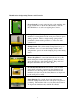

7. Safety Switch: This magnetic proximity switch is mounted
inside, near the top of the TSM-21. It is activated when the
Safety Buttons are depressed by the work piece.
8. Motor Carriage: The Motor Carriage is the yellow,
pivoting A-frame structure inside the machine. Both the
Router Motor and the Drill Motor are mounted to this
carriage. The forward and back carriage motion during the
machine cycle is provided by the Drive Cylinder.
9. Drive Cylinder: This double-acting pneumatic cylinder
connected to the Motor Carriage and the machine case,
moves the carriage through the routing and drilling phases
of the cycle. When the cylinder rod extends (moving the
carriage toward the rear) the router cuts the pocket. When
the cylinder rod retracts (moving the carriage forward) the
pilot drill bores the pilot hole into the pocket. Note: SQE
valves are replaced by elbow fittings in models with Serial
Number 62481 and higher.
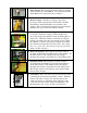
10. Router Stop Switch: This magnetic proximity switch is
mounted on the Router Stop Plate inside of the machine. At
the full extension of the routing stroke, the carriage
interrupts this switch to signal the start of the drilling stroke.
11. Drill Stop Switch: This magnetic proximity switch is
mounted inside the machine case near the Safety Buttons.
At the full extension of the drilling stroke, the carriage
interrupts this switch to signal the end of the cutting cycle.
The carriage returns to the neutral position and the clamp
releases the work piece.
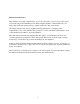
12. Control Box: The Control Box is the sheet metal enclosure
containing the electrical and pneumatic controls. Mounted
in the Control Box are the power switch and the power
outlets for the motors. Mounted on the underside of the
Control Box are the air inlet, the Pressure Regulator, the
Router Speed Control valve, and the solenoid valves.
4