
User's Manual


Operation
This module only allow 5V DC power source for operating power used, and a
battery backup 3V DC for RTC used (backup power is required if necessary). The host
side has a RS232 interface for host connection to receive or transmit relevant data
from or to host may be like PC or Embedded system which AP (Application Program)
executed. Antenna board should be connected to MB with a FFC cable when you
received. The blue LED on antenna board will be on and buzzer beep when power on
normally. At the meantime, this reader is operating and transmits RF (radio frequency)
signal for card reading. Once contactless card landing or closing within reading
distance, the orange LED will show the reading processing, and the green LED will
show the success of reading. Alternative the red LED will show any error when
reading process. May be buzzer beep also combine the LED indications in some case.
Connection
Type: FFC ZIF 1.0mm pitch 5 pin 90D upper contact (SCG BL113-05RU-TAND)
Pin definition:
Pin No.
Name Type Remarks
1 GND Input
2 RS232 RX Input
3 RS232 TX Output
4 VCC_5V Input
DC 5±0.05V
Max. 350mA
5 VCC_BKP_3V Input RTC power
1.8V (MIN.) 3.6V(MAX.)
Max. 5uA
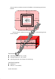
RF sensitive area in 2D, 3D
In order to maintain good reading ability of contactless module for the
requirements from EMV contactless certificate, the antenna board should be
positioned and considered in specified area as following described.