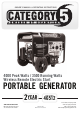
OWNER’S MANUAL & OPERATING INSTRUCTIONS 4000 Peak Watts / 3500 Running Watts Wireless Remote Electric Start PORTABLE GENERATOR 2yEAR LIMITED WARRANTY SAvE THESE INSTRuCTIONS Important Safety Instructions are included in this manual. MODEL NUMBER 46512 MADE IN CHINA REV 46512-20110301 10006 Santa Fe Springs Road Santa Fe Springs CA 90670 USA / 1 (877) 338-0999 www.championpowerequipment.
Have questions or need assistance? Do not return this product to the store! WE ARE HERE TO HELP! Visit our website: www.championpowerequipment.
46512 4000 Peak Watts / 3500 Running Watts Wireless Remote Electric Start PORTABLE GENERATOR Table of Contents Introduction. . . . . . . . . . . . . . . . . . . . . . . . . . . . . Introduction. . . . . . . . . . . . . . . . . . . . . . . . . . . Portable Power Generator. . . . . . . . . . . . . . . . . . Accessories . . . . . . . . . . . . . . . . . . . . . . . . . . . This Booklet. . . . . . . . . . .
ENGLISH 46512 Introduction Introduction Accessories Congratulations on your purchase of a Champion Power Equipment generator. CPE designs and builds generators to strict specifications. With proper use and maintenance, this generator will bring years of satisfying service. Champion Power Equipment manufactures and sells accessories designed to help you get the most from your purchase. To find out more about our covers, power cables and storm kits, please visit our web site at: www.
46512 ENGLISH Manual Conventions This manual uses the following symbols to help differentiate between different kinds of information. The safety symbol is used with a key word to alert you to potential hazards in operating and owning power equipment. Follow all safety messages to avoid or reduce the risk of serious injury or death. DANGER DANGER indicates an imminently hazardous situation which, if not avoided, will result in death or serious injury.
ENGLISH 46512 Safety Rules WARNING Read this manual thoroughly before operating your generator. Failure to follow instructions could result in serious injury or death. WARNING The engine exhaust from this product contains chemicals known to the state of California to cause cancer, birth defects, or other reproductive harm. DANGER Generator exhaust contains carbon monoxide, a colorless, odorless, poison gas. Breathing carbon monoxide will cause nausea, dizziness, fainting or death.
46512 ENGLISH DANGER Safety Rules WARNING Fuel and fuel vapors are highly flammable and extremely explosive. Fire or explosion can cause severe burns or death. Unintentional startup can result in entanglement, traumatic amputation or laceration. Rapid retraction of the starter cord will pull hand and arm towards the engine faster than you can let go. Unintentional startup can result in entanglement, traumatic amputation or laceration. Broken bones, fractures, bruises or sprains could result.
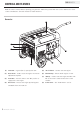
ENGLISH 46512 Controls and Features Read this owner’s manual before operating your generator. Familiarize yourself with the location and function of the controls and features. Save this manual for future reference. Generator 1 2 3 4 8 6 5 5 7 (1) Fuel Tank – 4 gallon (15 L) capacity fuel tank. (5) Recoil Starter – Used to start the engine. (2) Auto-Choke – Used to start the engine. No manual adjustment required. (6) Oil Filler Cap – Check and fill engine oil level.
46512 ENGLISH Controls and Features Power Panel 1 4 (1) Intelligauge – Three mode digital meter for running hours, voltage and hertz. (2) Ignition Switch (3) Circuit Breaker(s) – Protects the generator against electrical overload. (4) Battery Switch – Enables/disables starting electrically – via remotely or by Ignition Switch. (5) Ground Terminal – Consult an electrician for local grounding regulations.
Controls and Features Wireless Remote Control Power Panel Load Management Cont’d. This generator is equipped with a wireless remote control system for starting and stopping. The system consists of (4) main components: 1. Receiver Control Module (RCM) 2. Wireless Remote 3. Battery Switch 4. Ignition Switch The Remote Control functions are enabled when: 1. The Ignition Switch is in the “ON” position, AND 2. The Battery Switch is in the “ON” position.
46512 ENGLISH Controls and Features Parts Included Your 46512 Gasoline Powered Generator ships with the following parts: Wheel Kit –– –– –– –– –– –– –– –– –– –– –– –– 8” Wheel. . . . . . . . . . . . . . . . . . . . . . . . . Vibration Mounts. . . . . . . . . . . . . . . . . . . . Support Leg. . . . . . . . . . . . . . . . . . . . . . . Bushing. . . . . . . . . . . . . . . . . . . . . . . . . . Handle . . . . . . .
ENGLISH 46512 Assembly Your generator requires some assembly. This unit ships from our factory without oil. It must be properly serviced with fuel and oil before operation. If you have any questions regarding the assembly of your generator, call our help line at 1 (877) 338-0999. Please have your serial number and model number available. Install the Support Leg 1. Attach the support leg to the generator frame with cap screws (M8x16) and lock nuts (M8). 2.
46512 ENGLISH Connect the Battery 1. Remove the protective cover from the red (+) lead on the battery. 2. Attach the red (+) lead to the red (+) terminal on the battery with the cap screw (M6x10) and secure with the lock washer (M6). 3. Repeat steps 1-2 for the black (–) battery lead. Install the Spark Arrester Insert the spark arrester screen into the muffler outlet. Secure the spark arrester by placing the cover plate over the end of the screen, with the lettering facing outward.
ENGLISH 46512 Assembly Add Engine Oil Cont’d. NOTE Check oil often during the break-in period. Refer to the Maintenance section for recommended service intervals. NOTE The generator rotor has a sealed, pre-lubricated ball bearing that requires no additional lubrication for the life of the bearing. Add Fuel 1. Use clean, fresh, regular unleaded fuel with a minimum octane rating of 85 and an ethanol content of less than 10% by volume. 2. DO NOT mix oil with fuel. 3. Clean the area around the fuel cap.
46512 ENGLISH Operation Generator Location Wireless Remote Start Please consult your local authority. In some areas, generators must be registered with the local utility. Generators used at construction sites may be subject to additional rules and regulations. This generator must have at least five feet of clearance from combustible material. Leave at least three feet of clearance on all sides of the generator to allow for adequate cooling, maintenance and servicing.
ENGLISH 46512 Operation Connecting Electrical Loads Stopping the Engine 1. Let the engine stabilize and warm up for a few minutes after starting 2. Plug in and turn on the desired 120 Volt AC single phase, 60 Hz electrical loads. –– DO NOT connect 3-phase loads to the generator. –– DO NOT connect 50 Hz loads to the generator. –– DO NOT overload the generator. 1. Turn off all electrical loads connected to the generator.
46512 ENGLISH Operation Do Not Overload Generator Wattage Reference Chart Capacity Use the chart to determine approximate wattage requirements for your equipment. Follow these simple steps to calculate the running and starting watts necessary for your purposes. 1. Select the electrical devices you plan on running at the same time. 2. Total the running watts of these items. This is the amount of power you need to keep your items running. 3.
ENGLISH 46512 MAINTENANCE ANd STORAGE The owner/operator is responsible for all periodic maintenance . WARNING Never operate a damaged or defective generator . WARNING Oil Cont’d. NOTE Once oil has been added, a visual check should show oil about 1-2 threads from running out of the fill hole . If using the dipstick to check oil level, DO NOT screw in the dipstick while checking . Tampering with the factory set governor will void your warranty . WARNING Improper maintenance will void your warranty .
46512 ENGLISH Maintenance and Storage Spark Arrester Maintenance Schedule 1. Allow the engine to cool completely before servicing the spark arrester. 2. Remove the two screws holding the cover plate which retains the end of the spark arrester to the muffler. 3. Remove the spark arrester screen. 4. Carefully remove the carbon deposits from the spark arrester screen with a wire brush. 5. Replace the spark arrester if it is damaged. 6.
ENGLISH 46512 Maintenance and Storage Generator Maintenance Make certain that the generator is kept clean and stored properly. Only operate the unit on a flat, level surface in a clean, dry operating environment. DO NOT expose the unit to extreme conditions, excessive dust, dirt, moisture or corrosive vapors. CAUTION DO NOT use a garden hose to clean the generator. Water can enter the generator through the cooling slots and damage the generator windings.
46512 ENGLISH Specifications Engine Specifications Spark Plugs –– Engine. . . . . . . . . . 196 cc OHV CPE (Electirc Start) Recommended replacement spark plug: –– NGK BR6ES or equivalent Make certain the spark plug gap is 0.7 – 0.8 mm or (0.028 – 0.031 in.). Generator Specifications –– –– –– –– –– –– –– Running Wattage. . Starting Wattage. . AC Load . . . . . . . Phase. . . . . . . . . Frequency . . . . . . Fuel Capacity. . . . Weight. . . . . . . . . . . . . . .
Specifications Parts Diagram 19 REV 46512-20110301 ENGLISH 46512
46512 ENGLISH Parts List # Part Number Description Qty # Part Number Description Qty 1 168FDE-2-G1 Engine 1 53 GB6177 M8 Nut M8 14 2 ST02FD-02100011 Build Up (B) 1 54 GB5789 M8x45 Flange Bolt M8x45 2 3 ST02FD-02100012 Build Up (A) 1 55 ST02FD-0184-2.5(F) Frame 1 4 ST02FD-02110000-2.5 Rotor Comp 1 56 ST02FD-1151300C-1 Bottom Rubber II 2 5 ST02FD-02100005-2.
Specifications Engine Parts Diagram 21 REV 46512-20110301 ENGLISH 46512
46512 ENGLISH # Part Number Description Qty # Part Number Description 1 GB5789--86-FB6-8 Flange Bolt 6X8 6 57 ST168F--1130001 Carburetor Insulator 1 2 ST160F--1061200 Recoil Starter Knob 1 58 ST168F--1130002-CPE 1 3 ST160F--1061100-Q Recoil Starter Comp 1 Insulator Packing (No Asbestos) 4 ST160F--1061005 Recoil Starter Spring 1 5 ST160F--1061009 6 ST160F--1061001-A 7 ST188F--1060006 8 ST188F--1060005 9 GB5789--86-FB6-12 10 ST188F--1060003 11 ST188F--1060004 Recoi
Specifications Wiring Diagram 23 REV 46512-20110301 ENGLISH 46512
46512 ENGLISH Troubleshooting Problem Cause Solution Generator will not start No fuel Add fuel Faulty spark plug Replace spark plug Unit loaded during start up Remove load from unit Low oil level Fill crankcase to the proper level Generator will not start; Generator starts but runs roughly Place generator on a flat, level surface Choke in the wrong position. Adjust choke.
ENGLISH 46512 Warranty WARRANTY CHAMPION POWER EQUIPMENT 2 YEAR LIMITED WARRANTY Warranty Qualifications Champion Power Equipment (CPE) will register this warranty upon receipt of your Warranty Registration Card and a copy of your sales receipt from one of CPE’s retail locations as proof of purchase. Please submit your warranty registration and your proof of purchase within ten (10) days of the date of purchase.
46512 ENGLISH Warranty Champion Power Equipment, Inc (CPE), and the United States Environment Protection Agency (U.S. EPA.) Emission Control System Warranty Your Champion Power Equipment (CPE) engine complies with U.S. EPA emission regulations. YOUR WARRANTY RIGHTS AND OBLIGATIONS: The US EPA AND CPE are pleased to explain the Federal Emission Control Systems Warranty on your 1997 and later small off-road engine. New engines must be designed, built and equipped, at the time of sale, to meet U.S.
Warranty ENGLISH 46512 EMISSION CONTROL SYSTEM WARRANTY The following are specific provisions relative to your Emission Control System Warranty Coverage. Emission Control System Warranty (ECS Warranty) for 1997 and later model year engines): 1. APPLICABILITY: This warranty shall apply to 1997 and later model year engines). The ECS Warranty Period shall begin on the date the new engine or equipment is delivered to its original, end-use purchaser, and shall continue for 24 consecutive months thereafter. 2.
46512 ENGLISH Warranty EMISSION-RELATED PARTS INCLUDE THE FOLLOWING (using those portions of the list applicable to the engine) : Systems covered by this warranty Parts Description Fuel Metering System Fuel regulator, Carburetor and internal parts Air Induction System Air cleaner, Intake manifold Ignition System Spark plug and parts, Magneto ignition system Exhaust System Exhaust manifold, catalytic converter Miscellaneous Parts Tubing, Fittings, Seals, Gaskets, and Clamps associated with these