
User Manual

KENR8230-01
30 Page, (Dimensions: 39 inches x 28 inches)
ONE POSITION
TWO POSITION
THREE POSITION
VENTED
PRESSURIZED
RETURN ABOVE FLUID LEVEL
RETURN BELOW FLUID LEVEL
LINES CROSSING
LINES JOINING
TWO-WAY
THREE-WAY
FOUR-WAY
SPRING
CONTROL VALVES
RESTRICTION
LINE RESTRICTION
(FIXED)
2-SECTION PUMP
MAIN
AUX.
SPRING
(ADJUSTABLE)
VARIABILITY
LINE RESTRICTION
(VARIABLE)
LINE RESTRICTION
VARIABLE and PRESSURE
COMPENSATED
PRESSURE
COMPENSATION
PUMP: VARIABLE and
PRESSURE COMPENSATED
ENERGY TRIANGLES
HYDRAULIC PNEUMATIC
MEASUREMENT
PRESSURE
TEMPERATURE
FLOW
ROTATING SHAFTS
UNIDIRECTIONAL BIDIRECTIONAL
PUSH-PULL LEVER PEDALGENERAL MANUAL PUSH BUTTON SPRING
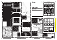
MANUAL CONTROL SYMBOLS
HYDRAULIC MOTORS
FIXED
DISPLACEMENT
VARIABLE DISPLACEMENT
NON-COMPENSATED
UNIDIRECTIONAL
BIDIRECTIONAL
HYDRAULIC PUMPS
FLUID STORAGE RESERVOIRS
CROSSING AND JOINING LINES
VALVE ENVELOPES
VALVE PORTS
BASIC COMPONENT SYMBOLS
FLUID CONDITIONER
PUMP or MOTOR
FLUID POWER SYMBOLS
FIXED
DISPLACEMENT
VARIABLE DISPLACEMENT
NON-COMPENSATED
UNIDIRECTIONAL
BIDIRECTIONAL
VALVES
PILOT CONTROL SYMBOLS
RELEASED PRESSURE
EXTERNAL RETURN
INTERNAL RETURN
REMOTE SUPPLY PRESSURE
SIMPLIFIED
COMPLETE
INTERNAL
SUPPLY PRESSURE
ACCUMULATORS
SPRING LOADED
GAS CHARGED
SOLENOID
or MANUAL
SOLENOID
and PILOT
SOLENOID and
PILOT or MANUAL
COMBINATION CONTROLS
SOLENOID
SERVO
THERMAL
DETENT
HYDRAULIC AND PNEUMATIC CYLINDERS
DOUBLE ACTING
SINGLE ACTING
BASIC
SYMBOL
SPRING
LOADED
CHECK VALVES
TWO
POSITION
INFINITE
POSITIONING
FLOW IN ONE
DIRECTION
FLOW ALLOWED IN
EITHER DIRECTION
THREE
POSITION
CROSS
FLOW
PARALLEL
FLOW
INTERNAL PASSAGEWAYS
NORMAL POSITION
AB
PT
AB
PT
SHIFTED POSITION
INFINITE POSITION
CONTROL VALVES
ATTACHMENT
MANUAL SHUTOFF
SHUTTLE PILOT
CONTROLLED
Hydraulic Symbols (Electrical)
Electrical Symbols Table
325-AG135 PK-14
Circuit Identification
Number
Wire Color
Wire Gauge
Harness identification code
This example indicates
wire 135 in harness "AG".
325-PK-14
Wire Gauge
Wire Color
Circuit Number
Identification
Wire Number Identification Codes
Current Standard
Previous Standard
Electrical Schematic Example
Hydraulic Schematic Example
325-PK
Wire Color
Circuit Number
Identification
B
A
Wire
Wire
(EXAMPLE VALVE)
Current Standard
Transducer
(Fluid)
Transducer
(Gas / Air)
G
Generator
Electrical Wire
Pressure Switch
M
Electric Motor
Pressure Switch
(Adjustable)
Temperature Switch
T
Pressure
Symbol
Temperature
Symbol
Level
Symbol
Flow
Symbol
Electrical Symbols (Electrical)
©
2008 Caterpillar
All Rights Reserved
Printed in U.S.A.
KENR8230-01
December 2008
432E, 434E, 442E, and 444E
Hydraulic System
432E:
BXE2200-UP
434E:
FSH900-UP
442E:
GKZ600-UP
444E:
LBE600-UP
Backhoe Loaders
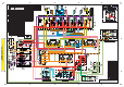
COMPONENT LOCATIONS
2
1
56
5
4
4
6
2
1
7
7
8
8
8
9
9
9
10
10
10
11
11
11
13
12
12
13
15
15
14
14
14
16
16
19
192021
202127
27
28
28
29
30
Tap Description
T1 Pump Discharge
T2 Load Sense
SOS Oil Sampling
TAP LOCATIONS
BACKHOE VALVE
29
The “E” series machines are equipped with a pilot controlled backhoe valve that is
visible with the floor plate at the rear of the cab removed.
This illustration shows a seven bank backhoe valve in a 432E Backhoe Loader.
SOS
Implement and
Steering Pump
HYDRAULIC OIL FILTER
SOS
Filter Bypass Switch
5
The 432E/434E/442E and 444E machines are all
equipped with the pilot controlled loader valve as
shown in this illustration.
The loader valve is accessed from below the floor
plate. The loader control valve group contains:
LOADER VALVE
E
27 28
D
C
B
A
Travel at high speeds over rough terrain causes bucket movement. The
optional Ride Control System acts as a shock absorber by absorbing
bucket forces, which stabilize the machine.
The Ride Control System components include; ride control relay (A), ride
control solenoids (B), ride control accumulator (C), and ride control
pressure switch (D).
Two solenoids are now used on the "E" Series machines Ride Control
System.
The Ride Control System, on machines with the optional autoshift
transmission, is controlled by the Machine ECM. The Machine ECM
monitors the position of the ride control switch and determines when to
operate the ride control system.
RIDE CONTROL
B
A
C
D
IMPLEMENT / STEERING PUMP
The implement and steering pump on the
432E, 434E, 442E and 444E machines is
similar to the "D" Series machines, but now
includes a torque control solenoid (not
visible). The torque control solenoid provides
an additional pump setting.
The implement and steering pump is located
below the floor plate in the cab. The pump
control valve (H) contains a torque control
spool adjustment screw (B) and a flow com-
pensator adjustment screw (A). The adjust-
ment screws and the load sensing pressure
tap (T2) are accessible from the cab.
Implement and
Steering Pump
1
F
View of mechanically controlled loader valve with floor plate removed.
Loader Valve
These illustrations show the implement and steering pump out of the machine. The following components are visible:
Torque control adjustment (A), Flow compensator adjustment (B), Load sensing pressure tap (T2), Inlet port (C),
Case drain port (D), Torque control solenoid (E), Discharge pressure tap (T1), Torque limiter (F), Outlet port (G)
B
C
D
THREE BANK VALVE (PILOT OPERATED)
G
H
J
K
L
M
P
R
N
E
G
A
B
E
F
D
C
D
E
C
A
B
T2
T2
T1
T2
T1
C
The 432E, 434E, 442E and 444E machines are equipped with hydraulically assisted master cylinders,
which decreases the amount of pedal effort when braking. This illustration shows the boosted brakes
valve group, which uses oil from the pilot accumulator to add boost to the master cylinder. The hydraulic
force multiplies the pedal effort so the operator can get more braking force with less effort.
The brake boost valves are connected to the master cylinder (A) at each brake pedal (B). Oil enters
the master cylinder through the supply hose (C) and exits the master cylinder through the return hose
(D). The oil flows to the service brakes through the hoses (E) at the bottom of the master cylinder.
The master cylinders can be removed from the machine from inside the operator's compartment.
This illustration shows a sectional view of the boosted brake valve group. When the brake pedal is
depressed, the boost brake valve moves to the left and inlet oil from the pilot manifold is directed
to the master cylinder.
BOOSTED BRAKES
Drain
SEVEN BANK VALVE
For other bank valve configurations see RENR6487 (Specifications Manual).
For other bank valve configurations
see RENR6487 (Specifications Manual).
SIDESHIFT
T3
The pilot manifold can also be
accessed with the floor plate
removed. The pilot pressure tap
(T3) is located on the pilot mani-
fold. The pilot manifold routes pilot
oil to and from the loader and
backhoe pilot control valves.
Pilot Manifold
View of pilot controlled backhoe valve with floor plate removed.
The hydraulic oil filter is located below the
machine at the left frame rail. The hydraulic oil
filter bypass switch is mounted to the oil filter
base.
Outlet manifold (A) Solenoid for the A circuit (H)
Auxiliary control valve (B) Makeup and relief valve (J)
Tilt control valve (C) B pilot line port (K)
Lift control valve (D) A pilot line port (L)
Inlet manifold (E) Priority Valve (M)
Load sensing relief valve (F) Dead engine lower valve (N)
Solenoid for the B circuit (G) A ports
(P)
B ports (R)
SOS
ECM
Loader Valve
"E" Series sideshift machines have a new slide frame with new externally serviceable slide frame
lock cylinders and reversible/replaceable wear plates (C). The lock cylinders can be serviced in the
field with standard tools. The stabilizers (D) are now externally adjustable. A powered sideshift
(bottom right illustration) is available, which allows the operator to hydraulically shift the backhoe
across the slider.
This illustration shows the optional powered sideshift attachment. The powered sideshift moves the
backhoe across the slider using two hydraulic cylinders (A). Wear pads (B) on the slider and powered
sideshift assembly are serviceable.
A
A
B
CD
To Wheel
Brake
Boost Brake
Valve
From Pilot
Accumulator
To Tank
Master
Cylinder
Slave
Cylinder
ABEDC
T3 Pilot Pressure
19 20 21
7
7
36
36
NOTE: Alpha numeric numbers are represented by the number only on the machine views.
18
29
30
18
17
17
34
34
33
33
32
32
31
31
23
22
23
22 25 26
25 26
Hydraulic Oil Filter
Temp Sensor
Filter Bypass
Switch
Temp Sensor
ITEM NAME 432E 434E
1 PUMP GP.
289-6370
2 HYDRAULIC TANK
246-5286
3 TANK GROUP
245-8777
4 COOLER
HYDRAULIC COOLER
5 FILTER
226-9747
6 HMU
210-6240
7
STEER CYLINDERS
7A FRONT
7B
REAR
8 LIFT CYLINDERS 214-9373
9 TILT CYLINDERS 192-3884
10
MP BUCKET CYL.(OPT)
11
STABILIZER CYLINDERS
11A LH
173-4565
11B RH
173-4565
12 BOOM CYLINDER
268-9049(S)
210-7076
268-9051(S)
246-9884
13 STICK CYLINDER
14 SWING CYLINDER
278-1971
15 BUCKET CYLINDER
210-7085(S)
210-7086
210-7095(S)
210-7096
16 E-STICK CYLINDER (OPT).
210-7097(S) / 210-7089
17
VALVE PILOT
17A VALVE PILOT (SWITCH)
297-4394
17B VALVE PILOT (SWITCH+DETENT)
297-4395
18 ACCUMULATOR
226-0420
19 RIDE CNTRL VALVE (OPT)
245-8780
20 RIDE CNTRL ACCMLTR (OPT)
162-3960
21 RIDE CNTR PRES. SWTCH(OPT)
131-9203
22 TEMP. SENSOR (OPT)
TEMP SENSOR
23 DIFF. PRES. SWITCH (OPT)
134-0404
25 COUPLER VALVE (See Volume 2)
231-2615
26 COUPLER CYLINDER (See Volume 2)
190-3085
27
LOADER VALVE (PL/IT) 3 BANK
LIFT SECTION
308-2157
TILT SECTION
308-2163
27C AUX SECTION
308-2159
27D INLET SECTION
PATTERN SWITCH VALVE
VALVE GP - CUSHION RELIEF (OPT)
32 VALVE GP - PILOT (BACKHOE)
33
VALVE GP - PILOT (LOADER)
267-2760
PRV MANIFOLD
300-4493
PO CHECK VALVE
308-3437
36 CHECK VALVE ADAPTER
165-7948
N/A
269-1083
COMPONENT LIST
24 ALL WHEEL STEER VALVE
442E 444E
249-6710 LH
249-6711 RH
249-6712 LH
249-6713 RH
210-7101 214-9372
268-9049(S)
210-7076
268-9051(S)
246-9884
210-7083(S)
210-7084
210-7093(S)
210-7094
210-7083(S)
210-7084
210-7093(S)
210-7094
256-3089 (OPT) 256-3089 (STD)
210-7085(S)
210-7086
210-7095(S)
210-7096
N/A
300-4491
206-3685
267-2758
N/A
N/A
MP BUCKET CYL.
H
28
LOADER VALVE (EST) 3 BANK
28 LOADER VALVE (3 BANK)
N/A
28A INLET SECTION
308-2156
293-8702
27A
27B
27 LOADER VALVE (3 BANK)
269-1081
N/A
N/A
28B TILT SECTION
308-2158
N/A
N/A
29
BACKHOE VALVE (SS) 7 BANK
29 BACKHOE VALVE (SS) 7 BANK
293-8701
29A BOOM SECTION
308-2149
29B STICK SECTION
308-2152
29C E-STICK SECTION
308-2153
29D OUTLET SECTION
308-2154
29E INLET MANIFOLD
308-2147
29F STABILIZER SECTION
308-2148
29G SWING SECTION
308-2150
29H BUCKET SECTION
308-2151
30
31
34
35
ITEM
VALVE
P1 LS RELIEF LOADER
P2 LS RELIEF BACKHOE
P3 HMU LS RELIEF
P4 TILT RE
P5 TILT HE
P6 LOADER AUX HE
P7 BUCKET RE & HE
P8 BOOM HE
P9 BOOM RE
P10a STICK HE
P10b STICK RE
P11 SWING RE + HE
P12 E-STICK RE + HE
P13 BACK PRESSURE CHECKVALVE
P14 FILTER BYPASS
P15 COOLER BYPASS
P16 STEERING CYL. RELIEF
P17 REAR WHEEL LINE RELIEF
P18 FLUSHING / MARGIN RELIEF
PR1 PILOT PRESSURE REDUCING
R1 LS DRAIN REGULATOR
LINE MAKE-UP/
RELIEF VALVE
STAB
BOOM
SWING
STAB
BUCKET
STICK
E-STICK
TANK (PLUGGED)
GAUGE
(PLUGGED)
SIDESHIFT CLAMP
SOLENOID VALVE
M14x2
SIDESHIFT CLAMP
M14x2
PUMP
(PLUGGED)
TANK
(LS DRAIN)
LOAD SENSE
RELIEF VALVE
LOAD
SENSE