RENR9968-02 July 2007 Systems Operation Testing and Adjusting C27 and C32 Generator Set Engines DWB1-Up (Generator Set) SXC1-Up (Generator Set) MED1-Up (Power Module) MEG1-Up (Power Module) WDR1-Up (Generator Set)
i01658146 Important Safety Information Most accidents that involve product operation, maintenance and repair are caused by failure to observe basic safety rules or precautions. An accident can often be avoided by recognizing potentially hazardous situations before an accident occurs. A person must be alert to potential hazards. This person should also have the necessary training, skills and tools to perform these functions properly.
RENR9968-02 3 Table of Contents Table of Contents Index Section Index ..................................................................... 65 Systems Operation Section General Information ................................................ 4 Electronic Control System Components ................. 6 Fuel System ......................................................... 10 Air Inlet and Exhaust System ............................... 14 Lubrication System ..............................................
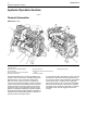
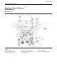
Systems Operation Section RENR9968-02 Systems Operation Section i02411347 General Information SMCS Code: 1000 g01205382 Illustration 1 Typical example (1) Electronic Control Module (ECM) (2) Turbocharger (3) Primary fuel filter and water separator (4) Engine oil filter base (5) Engine oil filters (6) Secondary fuel filter and fuel priming pump (7) Exhaust manifold The Mechanical Electronic Unit Injector (MEUI) fuel system is used on this engine.
RENR9968-02 Starting the Engine The engine’s ECM will automatically provide the correct amount of fuel in order to start the engine. Do not hold the throttle down while the engine is cranking. If the engine fails to start in twenty seconds, release the starting switch. Allow the starting motor to cool for two minutes before using the starting motor again. NOTICE Excessive ether (starting fluid) can cause piston and ring damage. Use ether for cold weather starting purposes only.
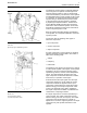
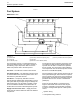
Systems Operation Section RENR9968-02 i02760232 Electronic Control System Components SMCS Code: 1900 g01205842 Illustration 2 Top view (1) Inlet air temperature sensor (2) Inlet air pressure sensor (3) Coolant temperature sensor (4) Atmospheric pressure sensor (5) Secondary engine speed/timing sensor (6) Coolant level sensor (7) Oil pressure sensor (8) Electronic Control Module (ECM)
RENR9968-02 7 Systems Operation Section The electronic control system is integrally designed into the engine’s fuel system and the engine’s air inlet and exhaust system in order to electronically control the fuel delivery. The electronic control system provides better timing control and fuel air ratio control in comparison to conventional mechanical engines. Injection timing is achieved by the precise control of the fuel injectors. Engine speed is controlled by adjusting the injection duration.
Systems Operation Section As an example, a moving solenoid plunger will perform work. By performing work, the component has functioned in order to regulate the engine. As an example, a control panel light or an alarm will provide information to the operator of the engine. These electronic components provide the ability to electronically control the engine operation.
RENR9968-02 The ECM also monitors all sensor inputs and the ECM provides the correct outputs in addition to acting as a power supply. Also, the ECM ensures the desired engine operation. The ECM is programmed with a selected factory engine rating. The ECM memory contains a personality module identification code. This code is used to avoid unauthorized tampering or switching of personality modules and other pertinent manufacturing information.
Systems Operation Section RENR9968-02 i02760777 Fuel System SMCS Code: 1250 g01155662 Illustration 6 (1) Cylinder head (2) Unit injector (3) Fuel transfer pump (4) Secondary fuel filter and priming pump (5) Fuel tank (6) Electronic Control Module (ECM) The fuel supply circuit is a conventional design for unit injector diesel engines.
RENR9968-02 • Injection duration • Engine cold mode status The mechanical electronic fuel system relies on a large amount of data from the other engine systems. The data that is collected by the ECM will be used in order to provide optimum performance of the engine. Low Pressure Fuel Supply Circuit The flow of fuel through the system begins at fuel tank (5). Fuel is drawn through the primary fuel filter and water separator (7) from the fuel tank by fuel transfer pump (3).
Systems Operation Section • Horsepower RENR9968-02 Electronic Unit Injector Mechanism • Torque curves • Engine speed (rpm) • Other characteristics The ECM, the personality module, the engine sensors, and the unit injectors work together in order to control the engine. Neither of the four can control the engine alone. The ECM maintains the desired engine speed by sensing the actual engine speed.
RENR9968-02 13 Systems Operation Section Electronic Unit Injector As the electronic unit injector mechanism transfers the force to the top of the electronic unit injector, spring (12) is compressed and plunger (15) is driven downward. This action displaces fuel through the valve in solenoid valve assembly (14), and into the return manifold to the fuel tank. As the plunger travels downward, the passage in barrel (16) is closed by the outside diameter of the plunger.
Systems Operation Section RENR9968-02 i02630349 Air Inlet and Exhaust System Air is forced from the aftercooler into inlet manifold (1). The air flow from the inlet port into the cylinders is controlled by inlet valves.
RENR9968-02 15 Systems Operation Section Turbocharger Illustration 12 g01319184 Turbocharger with wastegate (23) Canister (24) Actuating lever Illustration 11 g01319169 Turbocharger (12) (13) (14) (15) (16) (17) (18) (19) (20) (21) (22) Air inlet Compressor housing Compressor wheel Bearing Oil inlet port Bearing Turbine housing Turbine wheel Exhaust outlet Oil outlet port Exhaust inlet The turbocharger is mounted to the exhaust manifold of the engine.
Systems Operation Section RENR9968-02 Valves And Valve Mechanism Illustration 13 g01319198 Valve system components (25) (26) (27) (28) (29) (30) (31) Valve bridge Rocker arm Camshaft Rotocoil Valve spring Valve guide Valve The valves and the valve mechanism control the flow of inlet air into the cylinders during engine operation. The valves and the valve mechanism control the flow of exhaust gases out of the cylinders during engine operation.
RENR9968-02 17 Systems Operation Section Rotocoils (28) cause the valves to rotate while the engine is running. Valve rotation provides a longer service life. Valve rotation also minimizes carbon deposits on the valves. Adjustable idler gear (34) is designed to provide the required gear backlash between nonadjustable idler gear (35) and camshaft gear (33). If the cylinder head is removed, tolerances of the components will change. The components that change are the cylinder head and the head gasket.
Systems Operation Section Illustration 15 Lubrication system schematic RENR9968-02 g01087263
RENR9968-02 (1) Upper rear idler bearing (2) Oil passage for the rear housing (3) Middle rear idler bearing (4) Rear oil line (5) Lower rear idler (6) Oil passage to rocker arms and camshaft bearings (7) Oil passage to the heads (8) Oil gallery in the head (9) Camshaft bearings 19 Systems Operation Section (10) Shaft bearing for the live idler (11) Connecting rod with drilled oil passage (12) External oil line to rear gear train (13) Piston cooling jets (14) Lower front idler gear bearing (15) Main beari
Systems Operation Section RENR9968-02 i02414165 Cooling System SMCS Code: 1350 This engine has a pressure type cooling system that is equipped with a shunt line. A pressure type cooling system offers two advantages: • The cooling system can operate safely at a temperature that is higher than the normal boiling point of water. • The cooling system prevents cavitation in the water pump. Cavitation is the sudden formation of low pressure bubbles in liquids by mechanical forces.
RENR9968-02 21 Systems Operation Section Coolant Conditioner (If Equipped) Some conditions of operation can cause pitting. This pitting is caused by corrosion or by cavitation erosion. A corrosion inhibitor is a chemical that provides a reduction in pitting. The addition of a corrosion inhibitor can keep this type of damage to a minimum. The coolant conditioner element is a spin-on element that is similar to the fuel filter and to the oil filter elements.
Systems Operation Section RENR9968-02 i02290289 Basic Engine SMCS Code: 1200 Cylinder Block Assembly The cylinders in the left side of the block form a 65 degree angle with the cylinders in the right side. The main bearing caps are fastened to the block with four bolts, two bolts through each bearing cap and two bolts through the side of the block. The cylinder liners can be removed for replacement. The top surface of the block is the seat for the cylinder liner flange.
RENR9968-02 23 Systems Operation Section Camshaft Grounding Practices The camshaft has three lobes at each cylinder. These lobes allow the camshaft to operate the unit injector, the exhaust valves, and the inlet valves. The camshaft is supported in the cylinder head by seven journals which are fit with bearings. The camshaft gear contains integral roller dampers that counteract the torsional vibrations that are generated by the high fuel pressure during fuel injector operation.
Systems Operation Section NOTICE When jump starting an engine, the instructions in the Operation and Maintenance Manual, “Starting with Jump Start Cables” should be followed in order to properly start the engine. This engine may be equipped with a 12 volt starting system or with a 24 volt starting system. Only equal voltage for boost starting should be used. The use of a welder or of a higher voltage will damage the electrical system. The engine has several input components which are electronic.
RENR9968-02 25 Systems Operation Section The solenoid has windings (one set or two sets) around a hollow cylinder or a hollow housing. A plunger that is spring loaded is located within the solenoid housing. The plunger can move forward and backward. When the start switch is closed and electricity is sent through the windings, a magnetic field is created. The magnetic field pulls the plunger forward in the solenoid housing.
Systems Operation Section The starting motor rotates the engine flywheel at a rate that is fast enough to start the engine. The starting motor has a solenoid. When the start switch is activated, the solenoid will move the starter pinion in order to engage the pinion and the ring gear on the engine flywheel. The starting motor pinion and the ring gear will engage before the circuit between the battery and the starting motor is closed by the electric contacts in the solenoid.
RENR9968-02 27 Testing and Adjusting Section Testing and Adjusting Section 2. Install a 2P-8278 Tube As (SIGHT GAUGE) in the fuel return line. When possible, install the sight gauge in a straight section of the fuel line that is at least 304.8 mm (12 inches) long.
Testing and Adjusting Section RENR9968-02 If excessive air is not seen at the inlet to the fuel transfer pump, the air is entering the system after the fuel transfer pump. Proceed to Step 6. If excessive air is seen at the inlet to the fuel transfer pump, air is entering through the suction side of the fuel system. To avoid personal injury, always wear eye and face protection when using pressurized air. NOTICE To avoid damage, do not use more than 55 kPa (8 psi) to pressurize the fuel tank. 4.
RENR9968-02 29 Testing and Adjusting Section i02209818 Electronic Unit Injector - Test SMCS Code: 1290-081 This procedure assists in identifying the cause for an injector misfiring. Perform this procedure only after performing the Cylinder Cutout Test. Refer to Troubleshooting, “Injector Solenoid Circuit-Test” for more information. 1. Check for air in the fuel, if this procedure has not already been performed. Refer to Testing and Adjusting, “Air in Fuel - Test”. Electrical shock hazard.
Testing and Adjusting Section Illustration 23 RENR9968-02 g01123281 Illustration 25 Locating Top Center on the left side of engine Using 9S-9082 Engine Turning Tool (1) Timing bolt (2) Timing bolt location (3) Cover (1) Timing bolt (4) 9S-9082 Engine Turning Tool g01123312 Note: If the flywheel is turned beyond the point of engagement, the flywheel must be turned in the opposite direction of normal engine rotation approximately 45 degrees.
RENR9968-02 1. Determine if water and/or contaminants are present in the fuel. Check the water separator (if equipped). If a water separator is not present, proceed to Step 2. Drain the water separator, if necessary. A full fuel tank minimizes the potential for overnight condensation. Note: A water separator can appear to be full of fuel when the water separator is actually full of water. 2. Determine if contaminants are present in the fuel. Remove a sample of fuel from the bottom of the fuel tank.
Testing and Adjusting Section Note: There may be a noticeable change in the sound of the running engine when the air purge screw is tightened. The change in the sound of the engine is normal. Note: Failure to tighten all fittings could result in serious fuel leaks. 5. Clean any residual fuel from the engine components. RENR9968-02 7. Crank the engine for 30 seconds. Allow the starter motor to cool for two minutes. 8. Repeat Step 7 until the engine starts and the engine runs.
RENR9968-02 33 Testing and Adjusting Section 7. Close and tighten the air purge screw. High Fuel Pressure 8. Crank the engine for 30 seconds. Allow the starter motor to cool for two minutes. Excessive fuel pressure can cause fuel filter gaskets to rupture. The following conditions can cause high fuel pressure: 9. Close and tighten the fuel pressure regulating valve. • Plugged orifices in the fuel pressure regulating valve Note: Failure to tighten all fittings could result in serious fuel leaks.
Testing and Adjusting Section RENR9968-02 i02227448 Rear Gear Group - Time SMCS Code: 1206-531 Illustration 27 g01124671 Location of fuel pressure tap To check the fuel transfer pump pressure, remove the plug (1) from the fuel filter base. Install the pressure gauge and appropriate fittings from the 1U-5470 Engine Pressure Group and start the engine. Check the fuel pressure of the engine with the 1U-5470 Engine Pressure Group.
RENR9968-02 35 Testing and Adjusting Section Air Inlet and Exhaust System i02310859 Air Inlet and Exhaust System - Inspect SMCS Code: 1050-040 A general visual inspection should be made to the air inlet and exhaust system. Make sure that there are no signs of leaks in the system. Table 4 Required Tools Part Number Part Name Quantity 1U-5470 or 198-4240 Engine Pressure Group or Digital Pressure Indicator 1 Hot engine components can cause injury from burns.
Testing and Adjusting Section RENR9968-02 Back pressure is the difference in the pressure between the exhaust at the outlet elbow and the atmospheric air. Hot engine components can cause injury from burns. Before performing maintenance on the engine, allow the engine and the components to cool. Hot engine components can cause injury from burns. Before performing maintenance on the engine, allow the engine and the components to cool. NOTICE Keep all parts clean from contaminants.
RENR9968-02 1. Inspect the compressor wheel for damage from a foreign object. If there is damage, determine the source of the foreign object. As required, clean the inlet system and repair the inlet system. Replace the turbocharger. If there is no damage, go to Step 3. 2. Clean the compressor wheel and clean the compressor housing if you find buildup of foreign material. If there is no buildup of foreign material, go to Step 3. 3. Turn the rotating assembly by hand.
Testing and Adjusting Section RENR9968-02 i02227890 Inlet Manifold Pressure - Test Use the following procedure in order to use the 1U-5470 Engine Pressure Group to measure the inlet manifold pressure: SMCS Code: 1058-081 Table 5 Required Tools Part Number Part Name Quantity 1U-5470 or 198-4240 Engine Pressure Group or Digital Pressure Indicator 1 The efficiency of an engine can be checked by making a comparison of the pressure in the inlet manifold with the information given in the Technical
RENR9968-02 39 Testing and Adjusting Section A very high temperature can indicate that too much fuel is flowing to the cylinder. A malfunctioning fuel injection nozzle could cause this very high temperature. Use the 164-3310 Infrared Thermometer to check exhaust temperature. i02774006 Engine Valve Lash Inspect/Adjust SMCS Code: 1102-025 i02227927 Engine Crankcase Pressure (Blowby) - Test SMCS Code: 1215; 1317 To prevent possible injury, do not use the starter to turn the flywheel.
Testing and Adjusting Section RENR9968-02 If the measurement is not within this range adjustment is necessary. Refer to “Valve Lash Adjustment”. Note: See Testing and Adjusting, “Finding Top Center Position for the No. 1 Piston” for further details. Valve Lash Adjustment 2. With No. 1 piston at the top center position of the compression stroke, an adjustment can be made to the valves. Before any adjustments are made, lightly tap each rocker arm at the top of the adjustment screw.
RENR9968-02 b. Place the appropriate feeler gauge (5) between the inlet rocker arm and the inlet valve bridge. Turn inlet adjustment screw (4) while valve adjustment locknut (3) is being held from turning. Adjust the valve lash until the correct specification is achieved. Refer to Table 9. c. After each adjustment, tighten valve adjustment locknut (3) while valve adjustment screw (4) is being held from turning. Tighten to a torque of 30 ± 7 N·m (22 ± 5 lb ft). Recheck each adjustment. 7.
Testing and Adjusting Section RENR9968-02 Lubrication System i02414081 Engine Oil Pressure - Test SMCS Code: 1304-081 Measuring Engine Oil Pressure Work carefully around an engine that is running. Engine parts that are hot, or parts that are moving, can cause personal injury. Illustration 34 g00296486 1U-5470 Engine Pressure Group The 1U-5470 Engine Pressure Group measures the oil pressure in the system. This engine tool group can read the oil pressure inside the oil manifold.
RENR9968-02 43 Testing and Adjusting Section 2. Start the engine. Run the engine with SAE 10W30 or SAE 15W40 oil. The information in the engine oil pressure graph is invalid for other oil viscosities. Refer to Operation and Maintenance Manual for the recommendations of engine oil. Note: Allow the engine to reach operating temperature before you perform the pressure test. Note: The engine oil temperature should not exceed 115 °C (239 °F). 3.
Testing and Adjusting Section • The oil suction tube has a leak or a restricted inlet screen. Refer to Step 5. • The engine oil pump is faulty. Refer to Step 6. • Engine Bearings have excessive clearance. Refer to Step 7. 1. Check the engine oil level in the crankcase. The oil level can possibly be too far below the oil pump supply tube. This will cause the oil pump not to have the ability to supply enough lubrication to the engine components.
RENR9968-02 45 Testing and Adjusting Section i01126690 NOTICE Care must be taken to ensure that fluids are contained during performance of inspection, maintenance, testing, adjusting and repair of the product. Be prepared to collect the fluid with suitable containers before opening any compartment or disassembling any component containing fluids.
Testing and Adjusting Section RENR9968-02 • Wrong dipstick or guide tube • Sustained operation at light loads Excessive consumption of engine oil can also result if engine oil with the wrong viscosity is used. Engine oil with a thin viscosity can be caused by fuel leakage into the crankcase or by increased engine temperature.
RENR9968-02 47 Testing and Adjusting Section Cooling System i02630833 Cooling System - Check (Overheating) SMCS Code: 1350-535 Above normal coolant temperatures can be caused by many conditions. Use the following procedure to determine the cause of above normal coolant temperatures: Personal injury can result from escaping fluid under pressure. If a pressure indication is shown on the indicator, push the release valve in order to relieve pressure before removing any hose from the radiator. 1.
Testing and Adjusting Section 10. Check for loose drive belts. a. A loose fan drive belt will cause a reduction in the air flow across the radiator. Check the fan drive belt for proper belt tension. Adjust the tension of the fan drive belt, if necessary. Refer to Operation and Maintenance Manual, “Belt Inspect/Adjust/Replace”. b. Worn gears within the water pump will cause a reduction in coolant flow through the radiator. Check the gears within the water pump for any worn edges. 11.
RENR9968-02 49 Testing and Adjusting Section Personal injury can result from escaping fluid under pressure. This type of system prevents cavitation in the water pump. Cavitation is the forming of low pressure bubbles in liquids that are caused by mechanical forces. A pressure type cooling system helps to prevent pockets of air from forming. If a pressure indication is shown on the indicator, push the release valve in order to relieve pressure before removing any hose from the radiator. 1.
Testing and Adjusting Section RENR9968-02 Slowly loosen the pressure cap in order to relieve the pressure out of the cooling system. Then remove the pressure cap. The level of the coolant should not be more than 13 mm (0.5 inch) from the bottom of the filler pipe. If the cooling system is equipped with a sight glass, the coolant should be to the proper level in the sight glass.
RENR9968-02 51 Testing and Adjusting Section The 9S-8140 Pressurizing Pump is used to pressure test the radiator’s filler cap. This pressurizing pump is also used to pressure test the cooling system for leaks. Check the coolant frequently in cold weather for the proper glycol concentration. Use the 245-5829 Coolant/Battery Tester Gp in order to ensure adequate freeze protection. The tester can be used for antifreeze and coolants that contain ethylene or propylene glycol.
Testing and Adjusting Section RENR9968-02 1. Ensure that the engine is cool. Loosen the filler cap slowly and allow pressure out of the cooling system. Then remove the filler cap from the radiator. 2. Ensure that the coolant level is above the top of the radiator core. 3. Install the 9S-8140 Pressurizing Pump onto the radiator. 4. Take the pressure reading on the gauge to 20 kPa (3 psi) more than the pressure on the filler cap. 5. Check the radiator for leakage on the outside. 6.
RENR9968-02 53 Testing and Adjusting Section Start the engine. Run the engine until the temperature reaches the desired range according to the test thermometer. If necessary, place a cover over part of the radiator in order to cause a restriction of the air flow. The reading on the temperature indicator should agree with the test thermometer within the tolerance range of the water temperature indicator.
Testing and Adjusting Section RENR9968-02 Basic Engine i02287898 Piston Ring Groove - Inspect Refer to Special Instruction, SMHS7606, “Use of 1P-4000 Line Boring Tool Group” for the instructions that are needed to use the tool group. This tool is used in order to check the alignment of the main bearing bores. The 1P-3537 Dial Bore Gauge Group can be used to check the size of the bore.
RENR9968-02 55 Testing and Adjusting Section The 8T-0455 Liner Projection Tool Group can be used to check the liner projection. Refer to Special Instruction, “Use of the 8T-0455 Liner Projection Tool Group” for more information on the use of the tool.
Testing and Adjusting Section Illustration 47 RENR9968-02 g01086418
RENR9968-02 57 Testing and Adjusting Section 1. Install a new spacer plate gasket and a clean spacer plate. 2. Install the cylinder liners in the cylinder block without seals or bands. 3. Install the washers. 4. Install all bolts or the six bolts around the liner. Torque for bolts .......................... 95 N·m (70 lb ft) 5. Use the 8T-0455 Liner Projection Tool Group to measure the liner projection at “A”, “B”, “C” and “D”. 6. Record measurements for each cylinder. 7.
Testing and Adjusting Section RENR9968-02 3. Turn the flywheel at intervals of 90 degrees and read the dial indicator. 4. Take the measurements at all four points. The difference between the lower measurements and the higher measurements that are performed at all four points must not be more than 0.15 mm (0.006 inch), which is the maximum permissible face runout (axial eccentricity) of the flywheel.
RENR9968-02 59 Testing and Adjusting Section Face Runout (Axial Eccentricity) of the Flywheel Housing Illustration 51 g00285931 Bore Runout (Radial Eccentricity) of the Flywheel Housing Illustration 53 g00285934 8T-5096 Dial Indicator Gp 8T-5096 Dial Indicator Gp If you use any other method except the method that is given here, always remember that the bearing clearance must be removed in order to receive the correct measurements. 1.
Testing and Adjusting Section RENR9968-02 2. While the dial indicator is in the position at location (C) adjust the dial indicator to 0.0 mm (0.00 inch). Push the crankshaft upward against the top of the bearing. Refer to Illustration 55. Write the measurement for bearing clearance on line 1 in column (C). Note: Write the measurements for the dial indicator with the correct notations. This notation is necessary for making the calculations in the chart correctly. 3.
RENR9968-02 61 Testing and Adjusting Section i02031090 NOTICE Inspect the viscous vibration damper for signs of leaking and for signs of damage to the case. Either of these conditions can cause the weight to contact the case. This contact can affect damper operation. Vibration Damper - Check SMCS Code: 1205-535 Viscous Vibration Damper Illustration 57 g01034223 Typical example (1) (2) (3) (4) Adapter Damper assembly Pulley Bolts The vibration damper is installed on the front of crankshaft.
Testing and Adjusting Section RENR9968-02 Electrical System i02482495 Battery - Test SMCS Code: 1401-081 Most of the tests of the electrical system can be done on the engine. The wiring insulation must be in good condition. The wire and cable connections must be clean, and both components must be tight. Never disconnect any charging unit circuit or battery circuit cable from the battery when the charging unit is operated.
RENR9968-02 63 Testing and Adjusting Section Note: Refer to Operating Manual, SEHS9249, “Use of 4C-4911 Battery Load Tester for 6, 8, and 12 Volt Lead Acid Batteries” for detailed instruction on the use of the 4C-4911 Battery Load Tester. Refer to Operating Manual, NEHS0764, “Using the 177-2330 Battery Analyzer” for detailed instruction on the use of the 177-2330 Battery Analyzer. See Special Instruction, SEHS7633, “Battery Test Procedure” for the correct procedures to use when you test the battery.
Testing and Adjusting Section RENR9968-02 237-5130 Digital Multimeter Gp or 146-4080 Digital Multimeter Gp Illustration 61 g00283566 237-5130 Digital Multimeter Gp or 146-4080 Digital Multimeter Gp The 237-5130 Digital Multimeter Gp and the 146-4080 Digital Multimeter Gp are portable hand-held service tools with a digital display. These multimeters are built with extra protection against damage in field applications. Both multimeters are equipped with 7 functions and 29 ranges.
RENR9968-02 65 Index Section Index A Air in Fuel - Test..................................................... 27 Air Inlet and Exhaust System .......................... 14, 35 Turbocharger ..................................................... 15 Valves And Valve Mechanism ............................ 16 Air Inlet and Exhaust System - Inspect.................. 35 Air Inlet Restriction............................................. 35 Exhaust Restriction ............................................
Index Section L Lubrication System .......................................... 17, 42 M Main Bearings - Inspect......................................... 54 P Piston Ring Groove - Inspect................................. 54 R Rear Gear Group - Time........................................ 34 S Systems Operation Section ..................................... 4 T Table of Contents..................................................... 3 Testing and Adjusting Section ...............................
RENR9968-02 67 Index Section
©2007 Caterpillar All Rights Reserved Printed in U.S.A.