
User Manual

RENR9968-02 11
Systems Operation Section
•
Injection duration
•
Engine cold mode status
The m ec hanical electronic fuel system relies on a
large amount of data from the other engine systems.
The data that is collected by the ECM will be used in
order to provide optimum performance of the engine.
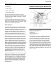
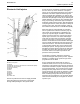
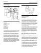
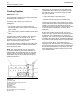
Low Pressure Fuel Supply Circuit
The flow of fuel through the system begins at fuel tank
(5). Fuel is drawn through the primary fuel filter and
water separator (7) from the fuel tank by fuel transfer
pump (3). The fuel transfer pump incorporates a
check valve that will allow fuel to flow around the
gears of the pump during priming of the fuel system.
The fuel transfer pump also incorporates a pressure
relief valve. The pressure relief valve is used in order
to protect the fuel system from extreme pressure.
Thefueltransferpumpisdesignedinorderto
produce an excess fuel flow throughout the fuel
system. The excess fuel flow is used by the system
to cool the fuel system components. The excess fuel
flow also purge s any air fro m the fue l system during
operation. Air that can become trapped in the fuel
system can cause cavitation that may damage the
components of the unit injector.
After leaving the fuel transfer pump, the fuel flows
to the ECM (6) in order to cool the E CM. Nex t, the
fuel flows to the secondary fuel filter and fuel priming
pump (4). The fu el priming pump is located on the
fuel filter base. The fuel filter base and the secondary
fuel filter also incorporate a siphon break that
prevents fuel from draining from the fuel system when
the engine is not in operation. The priming pump is
a hand operated pump that directs the flow of fuel
during the priming pump’s operation. The secondary
fuel filter is a two micron fuel filter. The fuel is filtered
in order t o remove small abras ive particles th a t will
cause premature wear t o fuel s ystem components.
The filtered fuel then flows out of the fuel filter and
returns to the passages in the fuel filter base. P rior to
exiting the fuel filter base, the fu el pressure and the
fuel temperature are sampled by the fuel pressure
sensor and by the fu el tempe r ature sensor. The
signals that are g enerated by the sensors are used
by the E CM in order to monitor the condition of the
engine’s components. This information is also used
to adjust the fuel delivery of the engine in order to
optimize efficiency.
The fuel is then transfered by the fuel supply lines
to the cylinder head (1). Only a portion of the fuel
that is supplied to the fuel injectors is used for
engine operation. This unused fuel is discharged into
the return passages of the fuel gallery. The fuel is
returned to the f uel tank by t he fuel return lines. A
continuous flow of fuel is experienced within the low
pressure fuel sys tem .
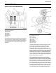
During engine operation, fuel injectors (2) receive
fuel from the low pressure fuel system. The injector
pressurizes the fuel to high pressure. The fuel is then
injected in to the cylind e r. The e xcess fuel is returne d
to the tank.
A pressure regulating valve is located in the fuel
return. The pressure re gulating valve allows the lo w
pressure fuel system to maintain a constant pressure.
A flow control orifice is also located in the fuel return.
The flow control orifice maintains a system back
pressure that is constant. The orifi
ce allow s the
flow of fuel through the system to be constant. This
prevents excessive heating of the fu el.
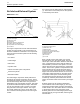
Fuel Heaters
Fuel heaters prevent the waxing of the fuel, a nd
the plugging of the fuel filters in cold weather. The
engine does not dissipate enough heat in order
to prevent waxing during cold weather conditions.
There are two types of fuel heaters that can be
used: therm ostatically controlled a nd self-adjusting.
Heaters that are not thermostatically controlled can
heat the fuel in excess of 65 °C (149 °F). Hig h fuel
temperatures can have the following effects:
•
Reduced engine efficiency
•
Fuel pump damage
•
Premature wear
Note: Never use fuel heaters without some type of
temperature regulator. Ensure that fuel heaters are
turned OFF during warm weather conditions.
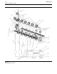
Fuel System Electronic Control
Circuit
The fuel system is equipped with an electronically
controlled, mechanically actuated unit injector in
each cylinder. A solenoid on each injector controls
the amount of fuel that is delivered by the injector. An
ECM sends a signal to each injector solenoid in order
to provide complete control of the engine.
There are two major components of the electronic
control system that are necessa ry in order to provide
control of the mechanical electronic unit injectors:
•
ECM
•
Personality m odule (storage for the ECM flas h file)
TheECMisthecomputerthatisusedtoprovide
control for all aspects of engine operation. The
personality module contains the software that
defines the characteristics of the engine control. The
personality module contains the operating maps. The
operating maps define the following characteristics
of the engine: