
User Manual

24 RENR9968-02
Systems Operation Section
NOTICE
When jump starting an engine, the instructions in the
Operation and Maintenance Manual, “Starting with
Jump Start C ables” should be followed in order to
properly start the engine.
This engine may be equipped with a 12 volt starting
systemorwitha24voltstartingsystem.Onlyequal
voltage for boost starting should be used. The use of a
welder or of a higher voltage will damage the electrical
system.
The engine has several input components which are
electronic. These components require an operating
voltage.
This engine is tolerant to common external sources
of electrical noise. Electromechanical buzzers
can cause disruptions in the power supply. If
electromechanical b uzzers are used near the system,
the e n gin e electro nics should be powered directly
from the battery system through a dedicated r elay.
The engine electronics should not be powered
through a common power bus with other devices that
are activate d by the E n g ine Contro l Switch (ECS).
Engine Electrical System
The electrical system can have three separate
circuits. The three circuits are the charging circuit,
the starting circuit, and the low amperage circuit.
Some of the electrical system components are used
in more than one circuit.
The charging circuit is in operation w hen th e e ng ine
is running. An alternator creates electricity for the
charging circuit. A voltage regulator in the circuit
controls the electrical output in order to maintain the
battery at full charge.
The starting circu it is in operation when the start
switch is activ ated.
The low amperage circuit and the charging circuit are
connectedthroughtheammeter.Thestartingcircuit
is not connected through the ammeter.
Charging System Components
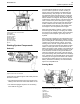
Alternator
The alternator is driven by the crankshaft pulley
through a belt that is a Poly-vee type. This alternator
is a three-phase self-rectifying charging unit. The
regulator is part of the alternator.
The alternator design has no need for slip rings or for
brushes. Th e only part of this alt ernator that moves
is the rotor assembly. All of the conductors that carry
current are stationary. The following components are
the conductors: the field winding, the stator windings,
six rectifying diodes, and the regulator circuit.
The rotor assembly has many magnetic poles with
air space between each of the opposite poles. The
poles have residual magnetism that produces a small
amount of magnet-like lines of force (magnetic field).
This ma gnetic fieldisproducedbetweenthepoles.
As the rotor assembly begins to turn between the
field winding and the stator windings, a small amount
of Alternating Current (AC) is produced in the stator
windings. The alternating current is produced from
the small magnetic lines of force that are created
by the residual magnet ism of the poles. The AC is
changed into Direct Current (DC) when the current
passes through the diodes of the rectifier bridge. M ost
of this current provides the battery charge and the
supply for the low amperage circuit. The remainder of
current is sent to the field windings. The DC current
flow through the field windings (wires around an iron
core) increases the strength of the magnetic lines
of force. These stronger magnetic lines of force
increase the amount of AC that is produced in the
stator windings. The increased speed of the rotor
assembly also increases the current output of the
alternator and the voltage output of the alternator.
The voltage regulator is a solid-state electronic
switch. The voltage regulator senses the voltage
of the system. The regulator then uses switches to
control the current to the field windings. This controls
the voltage output in order to meet the electrical
demand of the system.
NOTICE
The alternator should never be operated without the
battery in the circuit. The making or the breaking of an
alternator connection with a heavy load on the circuit
can cause damage to the regulator.