
User Manual

28 RENR9968-02
Testing and Adjusting Section
If excessive air is not seen at the inlet to the fuel
transfer pump, th e air is enter ing the system aft er
the fuel transfer pump. Proceed to Step 6.
If excessive air is seen at the inlet to the fuel
transfer pump, air is entering through the suction
side of the f uel system.
To avoid personal injury, always wear eye and face
protection when using pressurized air.
NOTICE
To avoid damage, do not use more than 55 kPa (8 psi)
to pressurize the fuel tank.
4. Pressurizethefueltankto35kPa(5psi).Donot
use m ore than 55 kPa (8 psi) in order to avoid
damage to the fuel tank. Check for leaks in the
fuel lines between the fuel tank and the fuel
transfer pump. Repair any leaks that are found.
Check the fuel pressure in order to ensure that
the fuel transfer pump is operating properly. For
information about checking the fuel pressure, see
Testing and Adjusting, “Fuel System Pressure -
Tes t” .
5. If the source of the air is not found, disconnect
the supply line from the fuel tank and connect an
external fuel supply to the inlet of the fuel transfer
pump. If this corrects the problem, repair the fuel
tank or the stand pipe in the fuel tank.
6. If the injector sleeve is worn or damaged,
combustion gases may be leaking into the fuel
system. Also, if the O-rings on the injector s leeves
are worn, missing, or damaged, combustion gases
may leak into the fuel system.
i02770540
Electronic Unit Injector - Adjust
SMCS Code: 1290-025
Table 1
Required Tools
Part
Number
Part Name Quantity
9U-7227
Injector Height Gauge
1
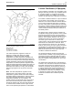
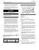
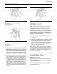
g01385601
Illustration 22
Injector Mechanism
(1)Rockerarm
(2) Adjustment screw
(3) Locknut
(4) 9U-7227 Injector Height Gauge
To make an adjustment to the unit injectors on
cylinders 4, 5, 6, 9, 11, and 12 use the following
procedure:
1. Put the No. 1 piston at the top center position
on the compression stroke. Refer to Testing and
Adjusting, “Finding Top Center Position for No. 1
Piston”.
2. Injector height gauge (4) is used in order to obtain
a dimension of 78.0 ± 0.2 mm (3.07 ± 0.01 inch).
Thedimensionismeasuredfromthetopofthe
unit injector to the machined ledge of the fuel
injector body.
3. Turn un it injector ad justment screw (2) clockw ise
until the correct height is obtained.
4. Hold the adj ustment screw in this po sition and
tightenlocknut(3)toatorqueof100±10N·m
(75±7lbft).
5. To make an adjustment to the unit injectors on
cylinders 1, 2, 3, 7, 8, and 10 remov e the timing
bolt. Turn the flywheel by 360 degrees in the
direction of engine rotation. The direction of
engine rotation is counterclockwise, as the engine
is viewed from the flywheel end. This will put the
number 11 piston at the top center position on the
compre ssion stroke.
6. Repeat Steps 3 through 4.
7. Remove th e timing bolt from the flywheel after all
the unit injector adjustments have been made.
Reinstall the valve mechanism covers.