
User Manual

RENR9968-02 39
Testing and Adjusting Section
A very high temperature can indicate that too much
fuel is flowing to the cylinder. A malfunctioning
fuel injection nozzle could cau s e th is very high
temperature.
Use the 164-3310 Infrared Thermometer to check
exhaust temperature.
i02227927
Engine Crankcase Pressure
(Blowby) - Test
SMCS Code: 1215; 1317
Table 7
Tools Needed
Part
Number
Part N ame Quantity
8T-2700
Blowby/Air Flow Indicator
1
Excessive blowby can cause a fouling or plugge d
condition i
n the following components:
•
The filter for the Closed Crankcase Ventilation
(CCV) syste
m
•
Turbocharger
•
Aftercooler
Damaged pis
tons or rings can cause too much
pressure in the crankcase. This condition will cause
the engine to run rough. The CCV can then become
restricted
in a very short time, causing oil leakage
at gaskets and seals that w ou ld not norma lly have
leakage. Blowby can also be caused by worn valve
guides or b
y a failed turbocharger seal.
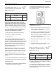
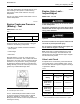
g00286269
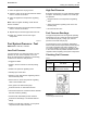
Illustra
tion 31
8T-2700 Blowby/Air Flow Indicator
The 8 T-2700 Blowby/Air Flow Indicator is used
to check the amount of blowby. Refer to Special
Instruc
tion, SEHS8712, “Using the 8T-2700
Blowby/Air Flow Indicator” for the test procedure for
checking the blowby.
i02774006
Engine Valve Lash -
Inspect/Adjust
SMCS Code: 1102-025
To prevent possible injury, do not use the starter
to turn the flywheel.
Hot engine components can cause burns. Allow
additional time for the engine to cool before mea-
suring valve clearance.
This engine uses high voltage to control the fuel
injector s.
Disconnect electronic fuel injector enable circuit
connector to prevent personal injury.
Do not come in contact with the fuel injector ter-
minals while the engine is running.
Note: Valve las h is measured between the rocke r
arm and the valve bridge. All measurements and
adjustments must be made with the engine stopped
and th e valves fully closed .
Valve Lash Check
An adjustment is not necessary if the measurement
of the valve lash is in the a cceptable range. Check
the valve lash while the engine is stopped. The range
is specified in Table 8.
Ta b l e 8
Quick Reference for Engine Valve Lash Setting
Inlet Valve
s
Exhaust Val
ves
Valve Lash
Setting
0.38 ± 0.08 mm
(0.015 ± 0.003
inch)
0.76 ± 0.08 mm
(0.030 ± 0.003
inch)
TC
Compression
Stroke of No.
1Piston
1-2-3-7-8-10 1-2-5-6-9-10
TC
Compression
Stroke of
No.
11 Piston
(1)
4-5-6-9-11-12 3-4-7-8-11-12
Firing Order
1-10-9-6-5-12-11-4-3-8-7-2
(2)
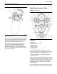
(1)
360° from TC compression stroke
(2)
Refer to I
llustration 32 in order to locate the No. 1 cylinder.