
User Manual

50 RENR9968-02
Testing and Adjusting Section
Slowly loosen the pressure cap in order to relieve the
pressure out of the cooling system. Then remo ve the
pressure cap.
The level of the coolant should not be more than
13 mm (0.5 inch) from the bottom of the filler pipe . If
the cooling system is equipped with a sight glass,
the coolant should be to the proper level in the sight
glass.
Tools for Testing the Cooling
System
Table 11
Tools Needed
Part
Number
Part Name
Quantity
4C-6500 Digital Thermometer 1
8T-2700
Blowby/Air F
low Indicator 1
9S-8140
Pressurizing Pump 1
9U-7400
Multitach Tool Group 1
245-5829
Coolant/Bat
tery Tester Gp 1
Making contact with a running engine can cause
burns from ho
t parts and can cause injury from
rotating parts.
When workin
g on an engine that is running, avoid
contact with hot parts and rotating parts.
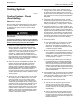
g00876179
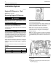
Illustration 38
4C-6500 Di
gital Thermometer
The 4C-6500 Digital Thermome ter is us ed for the
diagnosis
of overheating conditions and for the
diagnosis of overcooling conditions. This group can
be used to check temperatures in several different
parts of t
he cooling system. Refer to the tool’s
Operating Manual for the testing procedures.
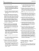
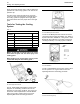
g00286269
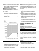
Illustration 39
8T-2700 Blowby/Air Flow Indicator
The 8T-2 700 Blowby/Air Flow Indicator is used to
check the air flow through the radiator core. Refer to
Special Instruction, S EHS8712, “Using the 8T-2700
Blowby/Air Flow Indicator” for the test procedure for
checking the blowby of a cooling system ’s radiator.
g00286276
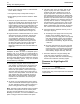
Illustration 40
9U-7400 Multitach
The 9U-7400 Multitach Tool Group is used to check
the fan speed for an engine. Refer to the tool’s
Operating Manual for the testing procedure.
g00286369
Illustration 41
9S-8140 Pressurizing Pump