
User Manual

RENR9968-02 57
Testing and Adjusting Section
1. Install a new spa cer p late gasket an d a clean
spacer plate.
2. Install the cylinder liners in the cylinder block
without seals or bands.
3. Install t he wa sh ers.
4. Install all bolts or the six bolts around the liner.
Torq ue for bolts .............. ............ 95 N·m (70 lb f t)
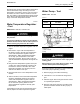
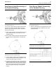
5. Use the 8T-0455 Liner Projection Tool Group to
measure the liner projection at “A”, “B”, “C” and
“D”.
6. Record measurements for each cylinder.
7. Add the four readings for each cylinder. Divide the
sum by four in order to find the average.
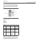
Table 18
Specifications
Liner Projection
0.025 to 0.152
mm
(0.0010to0.0060inch)
Maximum Variation In
Each Liner
0.051 mm (0.0020 inch)
Maximum Average
Variation Between
Adjacent Lin
ers
0.051 mm (0.0020 inch)
Maximum Variation
Between All Liners
0.102 mm (0.0040 inch)
Note: If the liner projection changes around the liner,
turn the liner to a new position within the bore. If the
liner proje
ction is not within speci fi cations, move the
liner to a different bore. Inspect the top face of the
cylinder block.
A thinner spacer plate should be installed if the
liner projection measurements are below the
specificat
ions. The spacer plate should also be
installed if the liner projection measurements are
low within a range. These plates are 0.076 mm
(0.0030 in
ch) thinner than the regular plate. The
plates will increase the liner projection. This will
increase the crush of the fire ring. Use these spacer
plates to
compensate for low liner projections that
are less than the 0.076 mm (0.0030 inch). Use
these spacer plates if the inspection of the top deck
reveals n
o measurable damage directly under the
liner flanges but the average liner projection is less
than 0.076 mm (0.0030 inch).
Do not exceed the maximum liner projection of
0.152 m m (0.0060 inch). The excessive liner
project
ion will contribute to cracking of the liner
flange.
When the liner projec tion is correct, pu t a tem p orary
mark on the liner and the spacer plate. Set the liners
aside.
Note: Refer to Disassembly and Assembly, “Cylinder
Liner - Install” for the correct final installati on
procedure for the cylinder liners.
When th e engine is ready for final assembly, the
following items must b e lubricate d before installation.
•
O-ring seals
•
Cylinder b lock
•
Upper filler band
Note: Apply liquid soap and/or clean engine oil
immediately before assembly. Avoid applying the
liquid soa p and/or clean e n gine oil to th e seals too
early. The seals may swell. This will caus e the seals
to be pinched underneath the liners during the liner
installation.
i02630856
Flywheel - Inspect
SMCS Code: 1156-040
Face Runout (Axial Eccentricity) of
the Flywheel
Ta b l e 1 9
Tools Needed
Quantity
8T-5096
Dial Indicator Gp
1
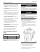
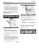
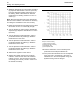
g00812156
Illustration 48
Checking face run out of the flywheel
1. Refer to Illustration 48 and install the dial indicator.
Always put a force on the crankshaft in the s ame
direction before the dial indicator is read. This will
remove any crankshaft en d c lea ran ce .
2. Set the dial indicator to read 0.0 mm (0.00 inch).