
User Manual

RENR9968-02 59
Testing and Adjusting Section
Face Runout (Axial Eccentricity) of
the Flywheel Housing
g00285931
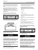
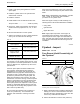
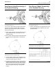
Illustration 51
8T-5096 Dial Indicator Gp
If you use any other method except the method that
is given here, always remember that the bearing
clearance must be removed in or der to receive the
correct measurements.
1. Fasten a dial indicator to the flywheel so the anvil
of the dial indicator will contact the face of the
flywheel housing.
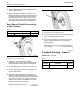
2. Use a rubber mallet and tap the crankshaft toward
the rear before the dial indicator is read at each
point.
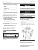
g00285932
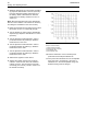
Illustration 52
Checking face runout of the flywheel housing
3. Turn the flywhee l while the dial indica to r is set at
0.0 mm (0.00 inch) at location (A). Read the dial
indicator at locations (B), (C) and (D).
4. The difference between the lower measurements
and the higher measurements that are performed
at all four points must not be more than 0.38 mm
(0.015 inch), which is th e maximum permissib le
face runout (axial eccentricity) of the flywheel
housing.
Bore Runout (Radial Eccentricity)
of the Flywheel Housing
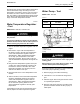
g00285934
Illustration 53
8T-5096 Dial Indicator Gp
1. Fasten a dial indicator to the flywheel so the anvil
of the dial indicator will contact the bore of the
flywheel housing.
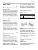
g00285932
Illustration 54
Checking bore runout of the flywheel housing
g00763974
Illustration 55