
User Manual

60 RENR9968-02
Testing and Adjusting Section
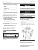
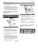
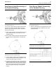
2. While the dial indicator is in the positio n at location
(C) adjust the dial indicator to 0.0 mm (0.00 inch).
Push the crankshaft upward against the top of
the bearing. Refer to Illustration 55. Write the
measurement for bearing clearance on line 1 in
column (C).
Note: Write the measurements for the dial indicator
with the correct notations. This notation is necessary
for making the calculations in the chart correctly.
3. Divide the measurement from Step 2 by two. Write
this number on line 1 in columns (B) and (D).
4. Turn the flywheel in order to put the dial indicator
at position (A). Adjust the dial indicator to 0.0 mm
(0.00 inch).
5. Turn the flywheel counterclockwise in order to
put the dial indicator at position (B). Write the
measurements in the chart.
6. Turn the flywheel counterclockwise in order to
put the dial indicator at position (C). Write the
measurement in the chart.
7. Turn the flywheel counterclockwise in order to
put the dial indicator at position (D). Write the
measurement in the chart.
8. Add the lines together in each column.
9. Subtract the smaller number from the larger
numbe r in column B and column D. Place this
number o n line III. The result is the horizontal
eccentricity (out of round). Line III in column C is
the vertical eccentricity.
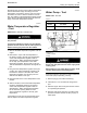
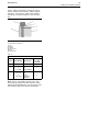
g00286046
Illustrati
on 56
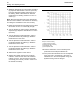
Graph for total eccentricity
(1) Total vertical eccentricity
(2) Total horizontal eccentricity
(3) Acceptable value
(4) Unacceptable value
10. Find the inte
rsection of the eccentricity lines
(vertical and horizontal) in Illustration 56.
11. If the point
of the intersection is in the “Acceptable”
range, the bore is in alignment. If the point of
intersection is in the “Not acceptable” range, the
flywheel hou
sing must be changed.