MODEL EC-C400 Instruction Manual EC -1 2 00 ON OF F UPRIGHT BIKE EC-C4OO Cateye Ergometer
HOW TO USE THIS MANUAL After first reading the "Start Guide," assemble the machine and give the Model EC-C400 Ergometor type Cat eye Fitness a try. Once you've become accustomed to the machine, read the "Operation Guide" and experiment with the EC-C400's wealth of functions. Make use of the "Reference Guide" as needed. CONTENTS Start Guide Operation Guide Starting with assembly ..................... 7 How to adjust each part ................. 10 Adapting the pulse sensor .............
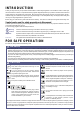
INTRODUCTION Thank you very much for your purchase of the Model EC-C400 Cateye Ergometer. The model EC-C400 is a new hightech exerciser with a built-in computerized training system designed specifically to promote cardiovascular fitness and overall endurance, the keystone of good health. With its endurance test program and four training programs, the ECC400 will help you to maintain or improve your physical strength in a fun and pleasant way.
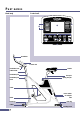
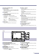
PART NAMES Main body Control unit HILL HR CONTROL 1 ADVANCE AEROBIC 2 3 2 3 AEROBIC 1 INTERVAL WEIGHT LOSS 1 2 3 TO OPERATE MANUALLY PRESS "QUICK" 4 FITNESS TEST STOP 5 HR CONTROL CONSTANT WATTAGE HILL 6 INTERVAL QUICK MODE START 7 8 9 Handlebar Control unit Saddle Handlebar lever Cable holder Handlebar post Seat post Handlebar post knob Spring lock pin Crank Power switch AC adapter inlet Pedal EC-1200 Front leg Rear leg Caster Leveling knob 4
1 Liquid crystal display (LCD) 2 Pattern display When Hill training or Interval training have been selected, the pattern (hill shape or training interval) which is set is indicated by a lamp. 3 Target pulse Lights and displays the target pulse when the HR control training has been selected. 4 Training select buttons FITNESS TEST .. Fitness test is selected. HR CONTROL ... HR control training is selected. CONSTANT WATTAGE ........ Constant wattage control training is selected. HILL ....................
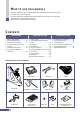
STARTING UP START GUIDE 1 Starting with assembly ............................................................. 7 2 How to adjust each part .......................................................... 10 3 Adapting the pulse sensor ..................................................... 12 4 Trying out the EC-C400 for the first time ........................... 13 5 The 6 kinds of programs ........................................................ 16 6 Using the EC-C400 without a data card ........................
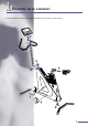
1 STARTING WITH ASSEMBLY Follow the steps starting from the next page and assemble the unit as shown in the figure below.
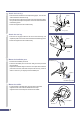
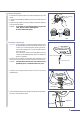
1 Attach the front leg. • Remove the two screws from the respective leg pipes. The one with casters should be used as front leg. • Place the front leg under the front end of the main body with casters facing forward, and adjust the position so that the screw holes meet the fastening points. • Fasten the leg with the two screws securely. Screw Front leg Front Caster 2 Attach the rear leg.
5 Attach the pedals. Crank • Use the No.15 end of the spanner to attach the pedals firmly to the cranks. • The right and left pedals are different, so be sure to check for R and L marks. • Tighten the right pedal by turning clockwise, and the left pedal by turning counterclockwise. Caution: If the pedals are not attached firmly enough to the crank, they can cause an irritating noise. Be sure to attach them firmly. No.15 end of the spanner Front Left 6 Right Install the control unit.
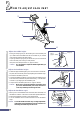
2 HOW TO ADJUST EACH PART HR OL CONTR CE IC ADVAN AEROB IC AEROB T LOSS WEIGH 3 HILL S ATE OPER PRES TO ALLY CK" MANU"QUI 1 2 3 VAL INTER K QUIC 1 AL INTERV 2 T STAR 3 HIL ANT GE CONST WATTA L E MOD HR OL CONTR 4 S FITNES TEST STO P 2 1 5 EC -12 00 ON OFF 6 1 2 3 Adjust the saddle height. • Pulling on the spring lock pin will enable you to move the seat post up or down. When the saddle is at the correct level for you, release the knob and move the seat post slightly.
4 Adjust the saddle angle. • Loosen the bolt of the seat pillar using the wrench provided. • Adjust the saddle to the desired angle. • Tighten the bolt of the seat pillar, fixing the angle of the saddle as desired. Seat pillar Wrench Adjust the pedal belt. 5 • The pedal belt length of the EC-C400 can be adjusted according to your shoes size. 6 The level knobs • Ideally, you should only use your exerciser on a hard, level floor.
3 ADAPTING THE PULSE SENSOR This model detects and displays your pulse rate during exercise by the earlobe sensor from your earlobe. Being a sensitive electronic part, the earlobe sensor must be handled with sufficient care. Important: When the chest-belt sensor is used, remove the earlobe sensor plug from the control unit. Signals from the chestbelt sensor cannot be received if the earlobe sensor is connected. Connect the pulse sensor.
4 TRYING OUT THE EC-C400 FOR THE FIRST TIME Turn on power and attach earlobe sensor AC adapter inlet 1 • Insert the AC adaptor into the AC adapter inlet at the rear of the • • • • 2 exerciser. Insert the plug of the AC adaptor into any household AC outlet (120V). Because of the danger of electric shock, do not Warning insert the AC plug into an outlet if your hands are wet. Caution: • Do not use any AC adaptor other than the one sup supplied with the Model EC-C400.
4 Press the START button to start • Press the button. • A buzzer sounds and the hill training display appears. • “START” as well as a mountain-like shape appear in the display, signifying that the hill training session has started. Start pedaling slowly. START Starting exercise CONSTANT WATTAGE HILL INTERVAL QUICK MODE START • This display shows various conditions as they apply to you during training.
Bring up the calories display by pressing 5 • Pressing the MODE MODE button button changes from the display with the exercise time, heart rate, and pedal cadence to that with the pedal loading level, wattage, and consumed calories. Pressing the MODE button again reverts to the first display. • You are now on the exerciser for your first ride. As you train, the pedal resistance will change and accordingly your pulse rate will change.
5 THE 6 KINDS OF PROGRAMS Fitness Test (physical fitness test) • Over a period of 10 minutes, you will encounter three different levels of pedal resistance. Your pulse will change in response to the different levels of resistance, and this change in pulse will be used to calculate your overall fitness level, also expressed is MOU (VO2 max). MOU stands for maximum oxygen uptake. The higher your overall fitness level, the greater your endurance.
Interval training (exercise + relief periods) • By switching back and forth between exercise and relief periods of varying length, interval training gives you the kind of program that professionals use to build their stamina and energy. • On the Model EC-C400, 3 patterns of interval training programs are preset for developing dashing power, speed, or your stamina respectively. Pattern-1: dash strength training (sprint power) 15 seconds exercise followed by a 45 second relief.
6 USING THE EC-C400 WITHOUT A DATA CARD The red card you used for your first session serves to input the type and conditions of training. But it is also possible to do the same thing without the card, by using the buttons on the control unit. 1 Turn on the power supply. 2 Select a training program. • Plug in the exerciser and turn on the power switch at the back of the main unit. • The initial display appears and prompts you to insert the card or to select a training mode.
3 Input training conditions. • The screen prompts you to set the training conditions. • The screen changes as shown here, and the initial value for age (40) is shown. • Your age can be increased or decreased as desired using the and buttons. The value changes rapidly if one or other button is pressed and held for longer than one second. • For example, press the button to change the value for age from 40 to 52. • After inputting your age, go on to the next screen by pressing the MODE button.
Starting exercising Start your exercise. 4 • When you have finished setting training conditions, press the START button and start exercise. The message “Start warming-up” is displayed to announce that the HR control training program has started. Start pedaling slowly. Reference: To skip the warm-up period and start a HR control training session immediately, press the button. • The pedal resistance can be changed arbitrarily during or after warm-up. To change the pedal resistance, press the or button.
6 Check your exercise record by scrolling the screen. • After training, you can view your workout data on the display. If the session has lasted for longer than 10 minutes, graphical information for the entire session can be viewed by scrolling the display using the and buttons. Pressing the button scrolls 5 minutes’ worth of data to the left while the button scrolls 5 minutes’ worth of data to the right. • After checking the session data, press the button to complete the program.
OPERATION OPERATION GUIDE 1 Training goals ......................................................................... 24 2 Your strength level and training index ............................... 26 3 Fitness test .............................................................................. 28 4 Fitness test (2) ........................................................................ 30 5 HR control training ...............................................................
1 TRAINING GOALS Training goals • Have you ever been out of breath after climbing a flight of stairs or after a brisk walk? When we are walking, running and even sleeping, our body is taking in oxygen and generating energy. Oxygen taken in by the lungs is sent to the entire body via the circulatory system. If the function of the circulatory system , i.e. aerobic power, is insufficient, we may experience being "out of breath" or experience yet other physical problems.
Target Pulse Rate Chart Terminology Maximum Heart Rate The heart rate increases according to the intensity of exercise, there is however a limit. The maximum heart rate that a person can sustain is called the "maximum heart rate". Generally the heart rate declines as we get older, this differs however between individuals, and is largely due to how much one exercises. Maxi mum The difference between heart rate and pulse rate pulse rate ( 204 - 0.
2 YOUR STRENGTH LEVEL AND TRAINING INDEX HR control training • In this program, the exercise intensity is set by the target pulse rate (beats per minute: bpm). Select your target pulse rate from the following table, based on your age and physical fitness level (PFL) from 1 to 5. • If the target you select is difficult, reduce the target pulse rate by 10 bpm. You need not work hard from the beginning, continuing is most important.
Interval training • In this program, select one of the 3 patterns depending on the power you want to improve. As for the exercise intensity, adjust the pedal resistance (torque: kg·m) during training, using and buttons. • This program is for people with a long history of exercise. • The following is a reference. Settings should match your physical fitness level and purpose. • Exercise for at least a 15 minute period. If possible a 20 ~ 30 minute period is even better.
3 1 FITNESS TEST Select the Fitness test program. • Attach the earlobe sensor, and press the Selecting training program FITNESS TEST training selection FITNESS TEST button to select the program. HR CONTROL CONSTANT WATTAGE HILL STOP 2 Input the conditions. Increase or decrease of numbers • Enter your age, weight, and sex in that order.
• Pressing the MODE button changes the numeric value displayed. Thus, the pedal loading level (resistance), wattage, and consumed calories can be checked. Caution: • If the pedal cadence is not detected for five seconds, a fitness test measurement cannot be carried out. “ERROR” blinks in the display and the test finishes. • If your pulse rate exceeds the upper pulse limit, “STOP EXERCISE” blinks in the display and the fitness test finishes forcibly.
4 FITNESS TEST (2) Physical Fitness Level (PFL) • There are five physical fitness levels: 1 ~ 5. These levels are relative evaluations that compare your maximum oxygen uptake (MOU), estimated by the Fitness test program, with the values of other people of the same age and sex (Physical Fitness Level Test Table).
Test Protocol • In the “Fitness test” program of the EC-C400 Ergometer, the workload (pedal resistance: torque) for the subsequent stage is determined depending on your pulse rate at the previous stage. The workload (pedal resistance: torque) will be increased along one of the routes illustrated below, depending on your pulse rate ™during the program. • The pulse rates specified below represent the protocol for a person of 20 years.
5 1 HR CONTROL TRAINING Selecting training program Select the HR control training program. • Attach the earlobe sensor, and press the training selection button to select the program. HR CONTROL FITNESS TEST HR CONTROL CONSTANT WATTAGE HILL STOP 2 Input the conditions. • Enter your age, target pulse, and desired exercise time, in that order.
5 Continue the training, maintaining the target pulse. • When finishing the warm-up phase, the pedal resistance is automatically adjusted (0.1 kg·m every 15 seconds so that the difference between the measurement value and the target value becomes (3 bpm. Thus, training can continue while the target pulse is being maintained. • You can adjust the pedal resistance using the and buttons. • Pressing the MODE button switches the numeric value displayed.
6 1 CONSTANT WATTAGE CONTROL TRAINING Select the Constant wattage control training program. • Attach the earlobe sensor, and press the training selection button to select the program. Selecting training program CONSTANT WATTAGE FITNESS TEST HR CONTROL CONSTANT WATTAGE HILL STOP 2 Input the conditions. Increase or decrease of numbers • Enter the wattage, your age, and exercise time in that order.
5 Continue the training, maintaining the wattage. • When warm-up finishes, the pedal resistance is automatically adjusted according to the pedal cadence so that the specified wattage is reached. Thus, training can continue while maintaining the wattage. • The wattage can be adjusted using the and buttons. • Pressing the MODE button switches the numeric value displayed.
7 1 HILL TRAINING Select the Hill training program. • Attach the earlobe sensor, and press the training selection button to select the program. Selecting training program HILL HR CONTROL CONSTANT WATTAGE HILL INTERVAL MODE 2 Input training conditions. • Enter your Exercise pattern, Age, and desired exercise time, in that order.
5 6 Continue the training. • The pedal resistance automatically changes according to the pattern. • A mountain-like shape represents a 15-minute interval. Every 15 minutes, the same mountain-like shape appears repeatedly. • You can change the pedal resistance using the and buttons. The pedal resistance can be changed in the range between the highest point of the convex shape (4.0 kg·m) and the lowest point of the concave shape (0.5 kg·m); it increases/decreases while the exercise pattern is maintained.
8 1 2 INTERVAL TRAINING Selecting training program Select the Interval training program. • Attach the earlobe sensor, and press the training selection to select the program. INTERVAL button CONSTANT WATTAGE HILL INTERVAL QUICK MODE START Input training conditions. Exercise patterns • Enter your Exercise pattern, Age, and desired exercise time, in that order.
5 6 Continue the training by repeating "exercise" and "rest." • The pedal resistance changes periodically according to the exercise pattern. • During the exercise period, you should pedal faster, then slower and lighter during the relief period. • You can change the pedal resistance using the and buttons. The pedal resistance can be changed in the range between the maximum of "exercise period" (4.0 kg·m) and the minimum of "relief period" (0.
9 1 QUICK START Select the Quick start program. • Attach the earlobe sensor, and press the training selection button to start the Quick start training program. • A buzzer sounds, and start the training. Reference: In the Quick start training program, no conditions are specified. The upper pulse limit is fixed to 160 bpm. QUICK Selecting training program CONSTANT WATTAGE HILL INTERVAL QUICK MODE START Start the warm-up. • "START WARM-UP" appears in the display. Start pedaling slowly.
3 Finish your exercise. Finishing training • To stop the program, press the button; the training program ends and the 5-minute cool-down period begins. The pedal resistance drops to the minimum of 0.5 kg·m. • To complete the cool-down phase, remain in cool-down mode. Data such as the remaining cool-down time (Count Down), your pulse rate, and other information are displayed. The total calories are accumulated.
10 HOW TO MAKE A DATA CARD START Program If you record your training conditions to this "Data Card", you can set the conditions merely by inserting the card into the card inlet of the control unit. You can start a program just by inserting the card and pressing the button, saving all the button operation process. To record your conditions to the data card, scratch off the appropriate silver part on the back of the card with a coin etc.
INTVL Sample data cards 9 MANU 1 TEST 0 A B C D INTVL 5 4 CONST 4 3 3 2 2 AUTO 1 1 0 D E F G H I A 9 C D E F G H I 32 years 16 minutes 1 MANU 9 8 8 HILL B Interval training Age: Exercise time: Pattern: MANU 9 0 TEST HR control training Age: 28 years Exercise time: 35 minutes Target pulse rate: 130 bpm MANU I 6 5 C H 7 CONST B G 8 HILL INTVL A F 9 6 TEST E Target pulse rate (bpm - 3 digits) MANU 7 AUTO R 2 AUTO 8 HILL A 3 • Speci
REFERENCE REFERENCE GUIDE 1 Chest-belt heart rate sensor ................................................. 46 2 Other useful functions ........................................................... 48 3 Troubleshooting ..................................................................... 49 4 Daily maintenance/repair service warranty/ additional parts ...................................................................... 50 5 Product specifications ...........................................................
1 CHEST-BELT HEART RATE SENSOR Use the wireless chest-belt heart rate sensor. In the EC-C400, the heart rate can be measured using the optional wireless chest-belt heart rate sensor instead of the earlobe sensor. Therefore, in cases where it is difficult to detect the heart rate using the earlobe sensor, the heart rate measurement can still be carried out accurately. The heart rate sensor receiver is embedded in the control unit.
Maintenance of the chest-belt heart rate sensor Warning After removing the battery from the sensor, dispose of it properly. Be sure to keep it out of the reach of small children. If through some accident it is swallowed, contact a physician immediately. Replace the battery. Battery life: approx. 2 years (if used for 1 hour per day) * The battery life shown in this manual is not definitive and it varies depending on the use environment.
2 OTHER USEFUL FUNCTIONS Select switch Change the units of weight. No. 1 Units of weight ON ............................. lb OFF ........................... kg • The units of weight can be changed using select switch No. 1 at the back of the control unit. • When the switch is “ON”, units are in lbs “pounds”. When the switch is “OFF”, units are in kg (“kilograms”). Reference: When the select switch settings have been changed and the power switch is then turned on, the new settings become activated.
3 TROUBLESHOOTING Troubleshooting In the following cases, the machine is not broken. Be sure to check the following before asking for the machine to be serviced. Problem Display does not appear. Item to check Is the power supply connected? Countermeasure Connect the AC adaptor correctly. (see page 13) ERROR or irregular display appears when you insert the data card. When the pulse (earlobe) sensor is used, the pulse rate displayed on the control unit remains at “0”.
4 DAILY MAINTENANCE /REPAIR SERVICE WARRANTY/ADDITIONAL PARTS Please observe the following to ensure that you will have many years of good use from your EC-C400 Ergometer. Caution • When the EC-C400 is not in use, shut the power switch OFF and disconnect the power cord from the outlet. • Do not wipe the main unit with organic solvents such as thinner, kerosine, gasoline and alcohol. When dirty, wipe the unit with a cloth soaked in a neutral detergent, than wipe well with a dry cloth.
5 PRODUCT SPECIFICATIONS Item Power source Power consumption Loading system Speed increasing mechanism Control system Display system Display functions Date input system Pulse sensor Exercise program Alarm function Buzzer sound User’s weight limit Dimension/weight Copyright© 2001 Cateye Co., Ltd. Printed in Japan ECMEC40-020226-2 Specifications Domestic power (AC120V) Max. approx.
CO.,LTD.