
Specifications


LCY-07084A-25
(Appendix)
Adjusting method of optimum DC bias voltage of common electrode driving signal
Photoelectric devices are very effective to obtain optimum DC bias voltage of common electrode driving
signal accurately, and theaccuracy is with 0.1V. (In visual examination method, the accuracy is about
0.5V because of the difference among individuals.)
Adjusting method of DC bias voltage using the photoelectric devices is as follows
Measurement of flicker
Adjust the DC baias voltage so as to minimize flicker at NTSC : 60Hz(30Hz) / PAL : 50Hz(25Hz).
Output voltage
Photo-electric device
LCD module
VCDC
Oscilloscope
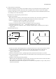
Fig. A Measurement system
Adjusting method of DC bias voltage
Measure the output voltage from Photoelectric device using the oscilloscope at the measurement
system of Fig. A.
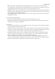
Then, change the DC bias voltage in small steps, and adjust it so as to minimize the flicker at
NTSC 60Hz(30Hz) / PAL : 50Hz(25Hz). (Fig.B)
DC bias : Optimum DC bias : Optimum + 1
Fig. B Waveforms of flicker