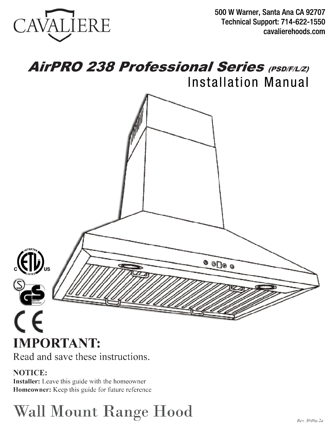
5 0 0WWa r n e r , Sa n t aAn aCA9 2 7 0 7 T e c h n i c a l Su p p o r t : 7 1 4 6 2 2 1 5 5 0 c a v a l i e r e h o o d s .
Important Safety Notice Read all Instructions before Installing and operating this appliance • • • • • The installation in this manual is intended for qualified installers, service technicians or persons with similar qualified background. Installation and electrical wiring must be done by qualified professionals and in accordance with all applicable codes and standards, including fire-rated construction. DO NOT attempt to install this appliance yourself.
Important Safety Notice Read all Instructions before Installing and operating this appliance • • • Clean ventilating fan frequently. Always use appropriate cookware and utensils size. Always use cookware appropriate for the size of the surface element. To reduce the risk of injury to persons in the event of a stove top grease fire: • • • SMOTHER FLAMES with a close-fitting lid, cookie sheet, or metal tray, then turn OFF the burner. BECAREFUL TO PREVENT BURNS.
Table of Contents INSTALLATION Tools needed....................................................3 Parts supplied...................................................4 Venting requirements.......................................5 Mount heights & clearance...........................5-6 Calculating vent system length.......................6 Venting methods & ductless conversion..........7 Charcoal filters & electrical requirements.......8 Preparation......................................................
Parts supplied: Range Hood (vary with model) Flappers Chimney Mounting Bracket Lower standard chimney Upper standard chimney Stainless Steel Baffle Filter(s) Grease Tunnel Air diverter (Optional re-circulating kit) Charcoal Filter (Optional re-circulating kit) Description Toggle Bolts Duct Set Body Hook Chimney Mounting Bracket This “Installation Guide and Users Manual” 5mm x 16mm Screw with Washer 4mm x 16mm Tapping Screw 4mm x 10mm Tapping Screw Optional: Toggle Bolt with Tapping Screw for Air D
Venting Requirements • • • • • • • Vent system must terminate to the outside (roof or side wall). DO NOT terminate the vent system in an attic or other enclosed area. DO NOT use 4” (10.2 cm) laundry-type wall caps. Use metal/aluminum vent only. Rigid metal/ aluminum vent is recommended. DO NOT use plastic vent. Always keep the duct clean to ensure proper airflow. Calculate the following figures before installation: 1. Distance from the floor to the ceiling. 2.
IMPORTANT: • A minimum of 6” round (standard for this range hood) or 3-1/4 x 10” rectangular duct (purchased separately) must be used to maintain maximum airflow efficiency. • Always use rigid type metal/aluminum ducts if available to maximize airflow when connecting to provided duct. • Please use Duct Run Calculation below to compute the total available duct run when using elbows, transitions and caps. • ALWAYS, when possible, reduce the number or transitions and turns.
Venting Methods • • This range hood is factory set for venting through the roof or wall. For non-vented (re-circulating) installations, see Ductless Conversion on Page 7. Vent work can terminate either through the roof or wall. To vent through a wall, a 90° elbow is needed. IMPORTANT: • • • • NEVER exhaust air or terminate duct work into spaces between walls, crawl spaces, ceiling, attics or garages. All exhaust must be ducted to the outside. Use metal/aluminum duct work only.
Charcoal Filter Installation NOTE: The charcoal filters are preinstalled if you purchased the range hood with re-circulating kit from us. 1. Remove stainless steel baffle filters on hood. 2. Remove the safety filter under the stainless steel baffle filters by unscrewing two screws, then position the charcoal filter and align the screw holes, reinstall and fasten two screws. 3. Reinstall the stainless steel baffle filters back to the hood. 4.
Preparation WARNING Excessive Weight Require three or more person to move and install this range hood. Spinal or other bodily injuries could occur if it is not followed. Advanced Preparations: 1. Read the entire installation guide and users manual thoroughly, understand instructions and warnings. 2. Be familiar with the controls of the range hood by reading through Range Hood Operations, Page 12. 3. Place the range hood on a flat, stable surface.
Installation WARNING Installations (refer to Page 4 for parts): Measure the distance between stove top and the bottom of Excessive Weight range hood. A distance of 28” to 31” is recommended*. Require three or more person to move and *Due to different ceiling height configurations, recominstall this range hood. Spinal or other bodimended height may not be applicable. ly injuries could occur if it is not followed. 1.
Installation (Continued) 7. Connect the range hood to a designated standard outlet (please refer the product label for the suitable voltage of this unit) or cut off the plug and connect three wires (black, white and green) to house wires and cap with wire connectors. Connect according to colors (i.e. black to black, white to white, and green to green). 8. Store excess wires in the wiring box. 9. Install both chimneys and tighten screws to secure the lower chimney to the range hood as shown in Figure 5. 10.
Range Hood Operations Power Power-Off Delay Decrease Value Blower Speed Indicator Light Increase Value Power-Off Delay Digital Timer Cleaning Reminder Indicator This range hood is designed to remove smoke, cooking vapors and odors from the cook top area. For best results, start the range hood before cooking and allow it to operate several minutes after the cooking is completed to clear all smoke and odors from the kitchen.
Range Hood Operations (Continued) Power Power-Off Delay Decrease Value Blower Speed Indicator • Light Increase Value Power-Off Delay Digital Timer Cleaning Reminder Indicator Controls: • Adjusting the timer function: • While the blower (motor) is not running, press and hold Decrease Value button over 3 seconds to enter timer mode. Adjust to desired period of delay off timer by pressing Increase Value or Decrease Value button (minimum 1 minute to maximum 9 minutes).
Wiring Diagrams Wiring Diagram (4 Speed) Wiring Diagram (6 Speed) NOTE: Wiring Diagrams shown above with GU10 light configuration. A transformer is required for MR16 Lights.
Measurements and Diagrams Installation Overview: A B C Mounting Bracket B A Qty: 6 PCS Qty: 6 PCS (For sheet rock only) Re-circulating kit exhaust (Re-circulating kit not shown) (Optional with glass canopy) C Qty: 4 to 8 PCS Hex Key Qty: 1 PCS (Vary with model) (Optional with glass canopy) Note: Type “A” anchors are designed for dry wall. Not to be used with any other types of walls.
Measurements and Diagrams (Continued) • All inch measurements are converted from millimeters, thus inch measurements are estimated.
Troubleshooting 1. If the range hood or halogen light does not operate after installation: • • Check if the range hood has been plugged in, make sure that all power has been turned back ON, fused not blown and all electrical wiring are properly connected. Swap out light assembly to working ones to determine whether it is caused by defective bulbs. See Replacing the light bulbs on Page 19. 2.
Use and Care Information Operations: • • • • • Read and understand all instructions and warnings in this manual before operating the appliance. Save these instructions for future reference. Always leave safety grills and filters in place. Without these components, operating blowers could catch on to hair, fingers and loose clothing. NEVER dispose cigarette ashes, ignitable substances, or any foreign objects into blowers. NEVER leave cooking unattended.
Maintenance SAFETY WARNING: Never put your hand into area housing the fan while the fan is operating! For optimal operation, clean range hood and all baffle/spacer/filter/grease tunnel/oil container regularly. Regular care will help preserve the appearance of the range hood. Cleaning Exterior surfaces: • Clean periodically with hot soapy water and clean cotton cloth. Do not use corrosive or abrasive detergent (e.g.
Warranty TO OBTAIN SERVICE UNDER WARRANTY: You must present proof of original purchase date. Please provide an original dated proof of purchase (sales receipt / invoice) in order to obtain service under warranty. One Year Parts Warranty: For one year from the date of original purchase, your local reseller will provide free of charge, non-consumable replacement parts or components that failed due to manufacturing defects.
Disclaimer Carefully inspect all items for damages before accepting delivery. note any damages on the freight bill or express receipt. request name and signature of the carrier’s agent and keep copy to support your claim. Upon acceptance of items, owner assumes responsibility for its safe arrival. Report damages to the carrier and file a claim immediately. Failure to do so may result in the denial of your claim. The carrier will furnish you with necessary forms for filing a claim.
Your Notes Page 22
Your Notes Page 23
Your Notes Page 24
Your Notes Page 25
5 0 0WWa r n e r , S a n t aA n aCA9 2 7 0 7 T e c h n i c a l S u p p o r t : 7 1 4 6 2 2 1 5 5 0 c a v a l i e r e h o o d s .