
Instructions / Assembly
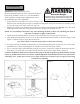
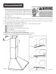
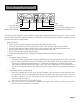
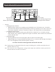
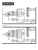
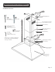
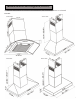
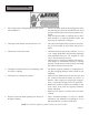
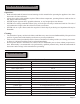
Table Of Contents
- Cavaliere_AP238_Series_PSD_F_L_Z_Wall_Manual-1
- Cavaliere_AP238_Series_PSD_F_L_Z_Wall_Manual.2
- Cavaliere_AP238_Series_PSD_F_L_Z_Wall_Manual.3
- Cavaliere_AP238_Series_PSD_F_L_Z_Wall_Manual.4
- Cavaliere_AP238_Series_PSD_F_L_Z_Wall_Manual.5
- Cavaliere_AP238_Series_PSD_F_L_Z_Wall_Manual.6
- Cavaliere_AP238_Series_PSD_F_L_Z_Wall_Manual.7
- Cavaliere_AP238_Series_PSD_F_L_Z_Wall_Manual.8
- Cavaliere_AP238_Series_PSD_F_L_Z_Wall_Manual.9
- Cavaliere_AP238_Series_PSD_F_L_Z_Wall_Manual.10
- Cavaliere_AP238_Series_PSD_F_L_Z_Wall_Manual.11
- Cavaliere_AP238_Series_PSD_F_L_Z_Wall_Manual.12
- Cavaliere_AP238_Series_PSD_F_L_Z_Wall_Manual.13
- Cavaliere_AP238_Series_PSD_F_L_Z_Wall_Manual.14
- Cavaliere_AP238_Series_PSD_F_L_Z_Wall_Manual.15
- Cavaliere_AP238_Series_PSD_F_L_Z_Wall_Manual.16
- Cavaliere_AP238_Series_PSD_F_L_Z_Wall_Manual.17
- Cavaliere_AP238_Series_PSD_F_L_Z_Wall_Manual.18
- Cavaliere_AP238_Series_PSD_F_L_Z_Wall_Manual.19
- Cavaliere_AP238_Series_PSD_F_L_Z_Wall_Manual.20
- Cavaliere_AP238_Series_PSD_F_L_Z_Wall_Manual.21
- Cavaliere_AP238_Series_PSD_F_L_Z_Wall_Manual.22
- Cavaliere_AP238_Series_PSD_F_L_Z_Wall_Manual.23
- Cavaliere_AP238_Series_PSD_F_L_Z_Wall_Manual.24
- Cavaliere_AP238_Series_PSD_F_L_Z_Wall_Manual.25
- Cavaliere_AP238_Series_PSD_F_L_Z_Wall_Manual.26
- Cavaliere_AP238_Series_PSD_F_L_Z_Wall_Manual.27
- Back
WARNING
Excessive Weight
Require three or more person to move and
install this range hood. Spinal or other bodi-
ly injuries could occur if it is not followed.
Installations (refer to Page 4 for parts):
Measure the distance between stove top and the bottom of
range hood. A distance of 28” to 31” is recommended*.
*Due to different ceiling height congurations, recom-
mended height may not be applicable.
Using references in 1. Height & Clearance on Page 5 and
Measurements and Diagrams on Page 15, mark the leveling point of the hood. Position two mounting screws
on the wall, leaving 1/8” space away from the wall.
Measure the width of the chimney then position the chimney-mounting brackets 2. directly above the hood-
mounting bracket, mark the leveling points and secure it using four mounting screws.
NOTE: Use threaded drywall anchors only when mounting the hood on sheet rock. Mounting the hood on
wall studs or lumbars is highly recommended.
Attach the hood-mounting bracket to the back of the hood with four screws as shown in Figure 1.3.
Align hood-mounting bracket to the screws on the wall and hook hood into place as shown in Figure 2 and 4.
Figure 3. Tighten screws to secure hood to the wall.
CAUTION: Make certain the range hood is secure before releasing!
For safety purpose, pre-drilled mounting holes are provided through the back of the hood. For a more secure 5.
installation, use as many mounting holes as needed to secure from the inside of hood.
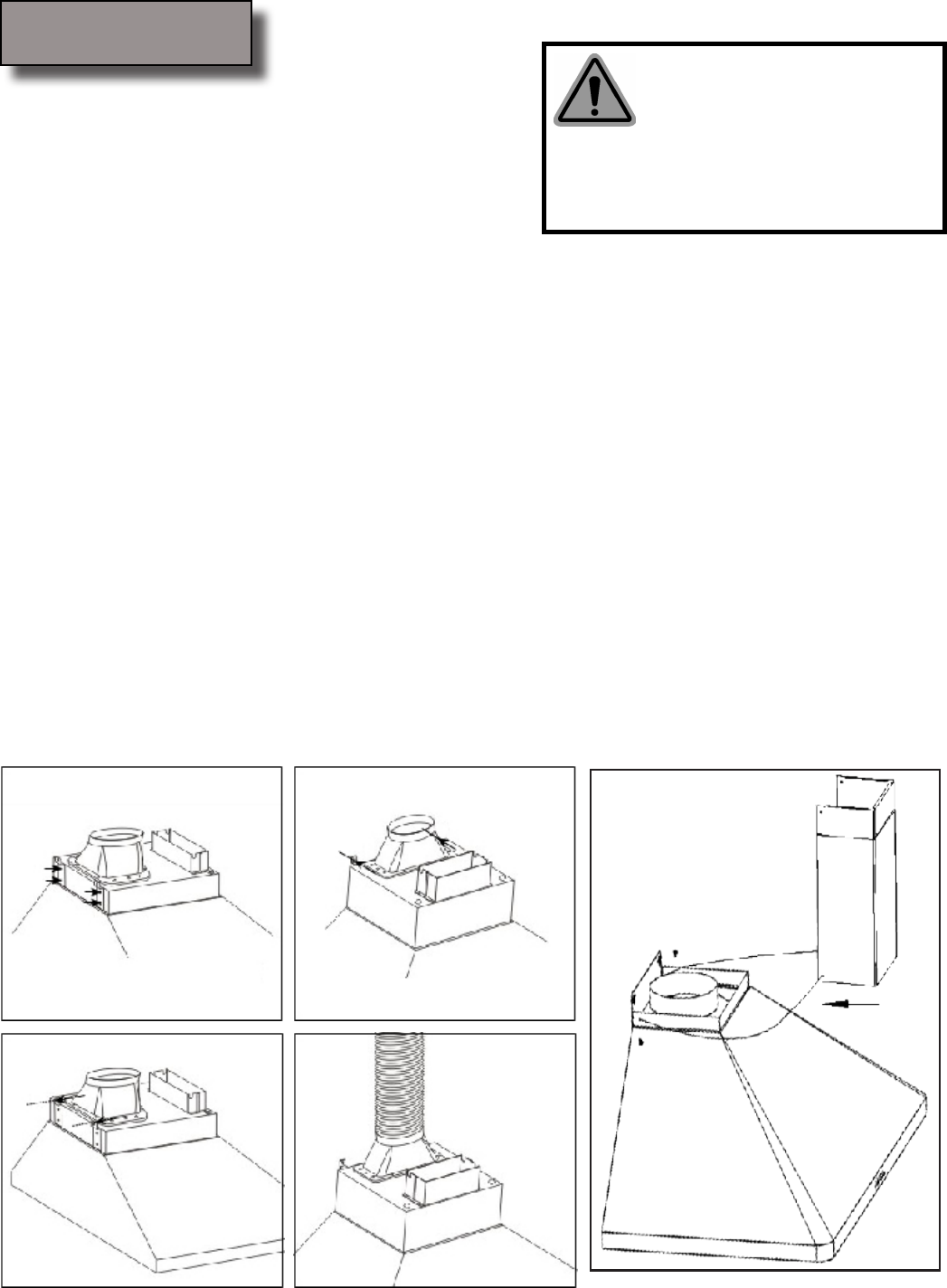
Use 6” round steel pipe (follow building codes in your area) to connect the exhaust on the hood to the duct-6.
work above. Use silver tape or duct tape to make all joints secure and air tight. Refer to Figure 4.
SAFETY WARNING: Risk of electrical shock. this range hood must be properly grounded. Make sure this
is done by qualied electrician in accordance with all applicable national and local electrical codes. Before
connecting wires, switch power off at service panel and lock service panel to prevent power from being
switched on accidentally.
Installation
Page 10
Figure 5
Figure 4
Figure 3
Figure 2
Figure 1