Installation Guide and Users Manual 198 Series Wall Mount Range Hood Suitable for: Standard Class “R” Class “E” Class “SP” Class IMPORTANT: Read and save these instructions. NOTICE: Installer: Leave this guide with the homeowner Homeowner: Keep this guide for future reference Wall Mount Range Hood Rev. 1016u.
Important Safety Notice Read all Instructions before Installing and operating this appliance • • • • • The installation in this manual is intended for qualified installers, service technicians or persons with similar qualified background. Installation and electrical wiring must be done by qualified professionals and in accordance with all applicable codes and standards, including fire-rated construction. DO NOT attempt to install this appliance yourself.
Important Safety Notice Read all Instructions before Installing and operating this appliance • • • Clean ventilating fan frequently. Always use appropriate cookware and utensils size. Always use cookware appropriate for the size of the surface element. To reduce the risk of injury to persons in the event of a stove top grease fire: • • • SMOTHER FLAMES with a close-fitting lid, cookie sheet, or metal tray, then turn OFF the burner. BECAREFUL TO PREVENT BURNS.
Table of Contents INSTALLATION Tools needed....................................................3 Parts supplied...................................................4 Venting requirements.......................................5 Mount heights & clearance...........................5-6 Calculating vent system length.......................6 Venting methods..............................................7 Electrical requirements....................................8 Preparation.........................................
Parts supplied: Range Hood (vary with model) Lower standard chimney Stainless Steel Baffle or Aluminum Filter(s) Flexible Duct Tube B A Qty: 6 PCS Upper standard chimney (For sheet rock only) Qty: 6 PCS C Qty: 4 PCS (For secure chimney) Chimney Mounting Bracket (1 pair) Remote Control Glass Canopy Screw Qty: 4 PCS (Optional with glass canopy) Hex Key Qty: 1 PCS (Optional with glass canopy) Light Inner Ring Opener Qty: 1 PCS Flappers (Optional w/ “R” Class Control) Page 4
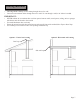
Venting Requirements • • • • • • • Vent system must terminate to the outside (roof or side wall). DO NOT terminate the vent system in an attic or other enclosed area. DO NOT use 4” (10.2 cm) laundry-type wall caps. Use metal/aluminum vent only. Rigid metal/ aluminum vent is recommended. DO NOT use plastic vent. Always keep the duct clean to ensure proper airflow. Calculate the following figures before installation: 1. Distance from the floor to the ceiling. 2.
IMPORTANT: • A minimum of 6” round (standard for this range hood) or 3-1/4 x 10” rectangular duct (purchased separately) must be used to maintain maximum airflow efficiency. • Flexible 6” round duct provided for convenience, always use rigid type metal/aluminum ducts if available to maximize airflow when connecting to provided duct. • Please use Duct Run Calculation below to compute the total available duct run when using elbows, transitions and caps.
Venting Methods • • This range hood is factory set for venting through the roof or wall. Vent work can terminate either through the roof or wall. To vent through a wall, a 90° elbow is needed. IMPORTANT: • • • • NEVER exhaust air or terminate duct work into spaces between walls, crawl spaces, ceiling, attics or garages. All exhaust must be ducted to the outside. Use metal/aluminum duct work only. Fasten all connections with sheet metal screws and tape all joints with certified Silver Tape or Duct Tape.
Electrical Requirements IMPORTANT: Observe all governing codes and ordinances. (Please consult with a qualified electrician for 220-Volt 50 Hz voltage) It is the customer’s responsibility: To contact a qualified electrical installer. To assure that the electrical installation is adequate and in conformance with National Electrical Code, ANSI/ NFPA 70 — latest edition*, or CSA Standards C22. 1-94, Canadian Electrical Code, Part 1 and C22. 2 No. 0-M91 - latest edition** and all local codes and ordinances.
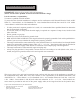
Preparation Advanced Preparations: 1. Read the entire installation guide and users manual thoroughly, understand instructions and warnings. 2. Be familiar with the controls of the range hood by reading through Range Hood Operations, Page 12. 3. Place the range hood on a flat, stable surface. Connect the range hood to a designated standard outlet (please refer the product label for the suitable voltage of this unit) and verify no debris has entered the vent openings, then turn on the range hood.
Installation DO NOT INSTALL THE RANGE HOOD BEFORE TESTING IT. MECHANICAL DAMAGE MIGHT HAVE OCCURRED DURING TRANSPORTION. Plug in the range hood to the USA/Canada 120V standard outlet (220V for Europe and other countries), test the blower and the lights before installing it. Installations (refer to Page 4 for parts): Measure the distance between stove top and the bottom of range hood. A distance of 28” to 31” is recommended*.
Installation (Continued) Figure 2 Figure 3 Figure 4 6. Store excess wires in the wiring box. 7. Install both chimneys and tighten screws to secure the lower chimney to the range hood as shown in Figure 5. 8. To avoid scratching the chimney, extend the upper chimney slowly and carefully to the chimney-mounting bracket and tighten screws as shown in Figure 6. 9. Turn power ON in control panel. Check all lights and fan operations. 10. Make sure to leave this Installation Guide for the homeowner.
Range Hood Operations & Wiring Diagram SV168/198 Series Standard Class (3 Speed Mechanical Control) Low Speed Power Switch High Speed Medium Speed Light Switch Turn On: • Press the speed control (Low Speed, Medium Speed, High Speed) switch to select the desired level of power. Once button is pressed, the previous speed mode will cancel. • Press the Light Switch to power on the lights. CAUTION: DO NOT touch the lights until switched OFF and cooled.
Range Hood Operations & Wiring Diagram (Continued) SV168/198 Series “R” Class (4 Speed Electronic Control w/ Remote) Power-Off Delay Control Remote Control Sensor Power / Fan Speed Control Speed / Timer Indicator Light Control This range hood is equipped with a credit card size remote control (approximately 20ft range), three built-in electronic controls, a powerful centrifugal squirrel cage motor, grease filters and two bright 12V 20W halogen lights.
Range Hood Operations & Wiring Diagram (Continued) SV168/198 Series “R” Class (4 Speed Electronic Control w/ Remote) Power-Off Delay Control Remote Control Sensor Power / Fan Speed Control Speed / Timer Indicator Light Control The credit card size remote control controls the power of the Lights , Power-Off Delay , Power (ON/OFF) and Fan Speeds: Quiet (F1), Low (F2), Medium (F3) and High (F4). The Power-Off Delay offers up to 99 minutes delay shutoff.
Range Hood Operations & Wiring Diagram (Continued) SV168/198 Series “R” Class Wiring Diagram NOTE: Wiring Diagrams shown above with GU10 light configuration. A transformer is required for MR16 Lights.
Range Hood Operations & Wiring Diagram (Continued) SV198 Series “E” Class (F20-Type 3 Speed Electronic Touch Control) Power Power-Off Delay Decrease Value Clock / Digital Display Light Increase Value This range hood is designed to remove smoke, cooking vapors and odors from the cook top area. For best results, start the range hood before cooking and allow it to operate several minutes after the cooking is completed to clear all smoke and odors from the kitchen.
Range Hood Operations & Wiring Diagram (Continued) SV198 Series “E” Class (F20-Type 3 Speed Electronic Touch Control) Power Power-Off Delay Decrease Value Clock / Digital Display • Light Increase Value Controls: • Lights: • Press Light button once to turn on the lights, and once again to turn off the lights. • Adjusting the clock function: • While the blower (motor) is off, press and hold Power button to enter clock setting.
Range Hood Operations & Wiring Diagram (Continued) SV198 Series “E” Class (R-Type 4 or 6 Speed Electronic Touch Control) Power Power-Off Delay Decrease Value Blower Speed Indicator Light Increase Value Power-Off Delay Digital Timer Cleaning Reminder Indicator This range hood is designed to remove smoke, cooking vapors and odors from the cook top area.
Range Hood Operations & Wiring Diagram (Continued) SV198 Series “E” Class (R-Type 4 or 6 Speed Electronic Touch Control) Power Power-Off Delay Decrease Value Blower Speed Indicator • Light Increase Value Power-Off Delay Digital Timer Cleaning Reminder Indicator Controls: • Adjusting the timer function: • While the blower (motor) is not running, press and hold Decrease Value button over 3 seconds to enter timer mode.
Range Hood Operations & Wiring Diagram (Continued) SV198 Series “E” Class Wiring Diagram (R-Type 4 Speed with GU10 Bulb) SV198 Series “E” Class Wiring Diagram (R-Type 6 Speed with GU10 Bulb) Page 20
Range Hood Operations & Wiring Diagram (Continued) SV198 Series “E” Class (S-Type 6 Speed Electronic Touch Control) Power Decrease Value Light Increase Value Blower Power Indicator Power-On Elapsed Digital Timer Blower Speed Indicator Power-Off Delay Digital Timer Light Power Indicator Power-Off Delay Timer Indicator This range hood is designed to remove smoke, cooking vapors and odors from the cook top area.
Range Hood Operations & Wiring Diagram (Continued) SV198 Series “E” Class (S-Type 6 Speed Electronic Touch Control) Power Decrease Value Light Increase Value Blower Power Indicator Power-On Elapsed Digital Timer Blower Speed Indicator Power-Off Delay Digital Timer Light Power Indicator • Power-Off Delay Timer Indicator Controls: • Adjusting the timer function: • While the blower (motor) is not running, press and hold Decrease Value button over 3 seconds to enter timer mode.
Wiring Diagram SV198 Series “E” Class Wiring Diagram (S-Type 6 Speed with GU10 Bulb) Page 23
Troubleshooting 1. If the range hood or halogen light does not operate after installation: • • Check if the range hood has been plugged in, make sure that all power has been turned back ON, fused not blown and all electrical wiring are properly connected. Swap out light assembly to working ones to determine whether it is caused by defective bulbs. See Replacing the light bulbs on Page 26-27. 2.
Use and Care Information Operations: • • • • • Read and understand all instructions and warnings in this manual before operating the appliance. Save these instructions for future reference. Always leave safety grills and filters in place. Without these components, operating blowers could catch on to hair, fingers and loose clothing. NEVER dispose cigarette ashes, ignitable substances, or any foreign objects into blowers. NEVER leave cooking unattended.
Maintenance SAFETY WARNING: Never put your hand into area housing the fan while the fan is operating! For optimal operation, clean range hood and all baffle/spacer/filter/grease tunnel/oil container regularly. Regular care will help preserve the appearance of the range hood. Cleaning Exterior surfaces: • Clean periodically with hot soapy water and clean cotton cloth. Do not use corrosive or abrasive detergent (e.g.
Maintenance (Continued) WARNING Hazard of Burns! Light bulb become extremely hot when turned on. DO NOT touch bulb until switched off and cooled. Touching hot bulbs could cause serious burns. Replacing the Light Bulb Using the Inner Ring Opener: • Make sure the range hood is unplugged or turn OFF breaker. • Make sure the lights are cool to touch, carefully align the arrow on the inner ring with the arrow on the outer ring where it says OPEN with the Inner Ring Opener as shown in Figure 1.
Warranty TO OBTAIN SERVICE UNDER WARRANTY: You must present proof of original purchase date. Please provide an original dated proof of purchase (sales receipt / invoice) in order to obtain service under warranty. One Year Parts Warranty: For one year from the date of original purchase, your local reseller will provide free of charge, non-consumable replacement parts or components that failed due to manufacturing defects.
Disclaimer Carefully inspect all items for damages before accepting delivery. note any damages on the freight bill or express receipt. request name and signature of the carrier’s agent and keep copy to support your claim. Upon acceptance of items, owner assumes responsibility for its safe arrival. Report damages to the carrier and file a claim immediately. Failure to do so may result in the denial of your claim. The carrier will furnish you with necessary forms for filing a claim.
Cavaliere 7372 Doig Drive Garden Grove, California 92841 Tel: 714-622-1550 Fax: 714-622-1559 http://www.cavalierehoods.