
Installation Sheet

Installation Instructions for CAVILOCK CL400 ADA Magnetic
Privacy Handle
CL400 ADA Snib/Snib
Privacy Handle
CL400 ADA Snib/Emergency
Privacy Handle
CL400 ADA Snib One Side
Privacy Handle
3
Door face
1
Door cut out
template
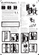
1. Mark a line on the face of the door where
the centre of the handle is to be positioned.
Align the centre line on the door cut out
template with the centre line on the door.
Follow the instructions on the template.
Transfer
lines
across
front edge
of door
2. Mark two holes in the centre of the door
thickness in the positions shown. Using these
marks, drill two 2.5mm (3/32”) diameter holes
to a depth of 35mm (1-3/8”).
5. Fit the snib privacy side handle to the
chassis as follows (if installing a snib/snib
privacy handle install ONE of the side handles
only):
a. Align the recess in the back of the snib
button with the arm of the locking slider.
b. Slide the front flange of the handle under
the heads of the 3x side handle to chassis
screws. Tighten the screws.
Top edge
of side
handle
61.75mm
(2-7/16”)
6
Front
flange
5
a
a
b
b
6. Close the door and mark a horizontal
line on the closing jamb 61.75mm
(2-7/16”) down from the top edge of the
side handle.
Locking
slider arm
Recess
Reversed
View
3mm (1/8”)
gap under
head
Side
handle to
chassis
screws
4
4. Fit the 6x side handle to chassis screws.
Leave a 3mm gap (1/8”) between the underside
of the screw head and the chassis.
c
d
e
i
(2)
j (6)
k (3)
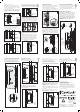
Privacy Side Handle (Left)
a
b
Privacy Side Handle Box
Privacy Side Handle (Right)
h (2)
g
f
q (4)
s (2)
r
o (2)
m (2)
p
n
(red)
n
(green)
t (2)
u
o
p
Striker Nuts (2)
Striker Box
Striker Body
Striker Mounting Wood Screws (4)
Privacy Striker Face Plate
Striker Face Plate Screws (2)
q
s
r
Note: Components will vary between the ‘Snib/Emerg’,
‘Snib/Snib’ and ‘Snib One Side’ versions.
Straight handle option shown.
l
m
n
c
d
e
f
g
h
i
j
Privacy Face Plate
Privacy Chassis Box
Privacy Chassis
Plunger
Shroud
Plunger Nut
Spring Reservoirs (2)
Chassis Mounting Screws (2)
Side Handle to Chassis Screws (6)
Handle Joining Screws (2)
Clip-In Indicators (2)
Face Plate Screws (3)
k
Emergency Release Button
(Where Applicable)
l
b
4
PAGE
3
PAGE
2
Component Drawings
PAGE
Door Preparation Fitting the First Side HandleFitting the Chassis Fitting the Striker
3. Remove the face plate screw and face
plate from the chassis. Align the chassis
with the centre of the door thickness.
Screw the chassis to the door (using the
2x chassis mounting screws) through the
slotted holes at the top and bottom of the
chassis. DO NOT fully tighten the screws.
Realign the chassis with the centre of the
door thickness. When happy with the chassis
position, fully tighten the screws.
Go to page 5 (overleaf)
Correct alignment
✓
==
Slotted
hole
Centre of door
thickness
Snib privacy
side handle
Chassis
mounting
screws
WARNING: THE STRIKER CONTAINS A STRONG MAGNET
IRON FILINGS - Magnets will attract shavings from iron or ferrous metals which may be hard to
remove. Keep the striker a safe distance away from these materials.
DANGER FOR CHILDREN - Magnets may cause serious injury if swallowed. Keep out of reach of children.
CRUSHING, BLISTERS AND CUTS - Fingers may become caught between magnets resulting in crushing,
blisters or cuts.
BREAKING OR CHIPPING - It is possible that magnets could chip or shatter on contact with other hard
materials, resulting in chips flying off at high speed into someone’s eye. Chips can also be very sharp -
treat them as you would broken glass.
MAGNETICALLY SENSITIVE ITEMS - Keep a safe distance between the magnet and all objects that can
be damaged by magnetism (e.g. mechanical watches, pacemakers, cell phones etc.).
DISPOSAL - Magnets should be disposed of carefully and in accordance with your local regulations.
5mm
(13/64”)
5mm
(13/64”)
Ø 2.5mm
(3/32”)
2
Door
thickness
1
PAGE
Plunger Adjustment Spanners (2)
Tools (contained in Privacy Chassis Box)
CL400 Allen Key
t
u
7. Open the door. Transfer the horizontal line
across the centre of the closing jamb. This
line represents the top of the striker cut out.
A double-sided striker cut out template has
been provided:
- Use template labelled ‘FLUSH striker
template’.
32 40
32 40
40 32
40 32
2
3
7
C
L
5
4
6
Horizontal
line
Centre of
closing jamb/
centre of
door closing
position
C
L
7
Note: these instructions are demonstrated
on a recessed closing jamb, however, the
same method applies to a flat closing jamb.
a
Striker
template
Locking
slider
arm
Raised shroud:
offers a greater
level of security.
Flush shroud:
decreased
security.
Before you Start:
1. This handle has been manufactured to specifications which cannot be altered by the installer. These include
Handle type, Configuration, Handing and Door thickness range. Refer to the information printed on the Side
Handle and Chassis boxes to ensure you have purchased a handle with the correct specifications for your
situation. If the specifications are incorrect you will need to exchange the handle.
2. Security: the CL400 handle varies in security depending on the version and
configuration. Handles supplied with a raised shroud provide a greater level of
security than those with a flush shroud, however, it is important to note that the
CL400 handle should not be installed in situations where a high level of security
is required, e.g. external entry points or high security internal doorways.
3. Component drawings have been provided. Please familiarise yourself with
the components and check the package to ensure nothing is missing. Note:
Components may vary slightly between configurations.
4. To ensure the handle latches accurately, it is essential that the door is adjusted for height and is parallel
with the closing jamb when closed before installing the handle and striker.
5. This is a metric handle. Accurate measurements are shown in millimetres. Conversions to inches are
approximate.
6. NZS4121:2001: To comply with NZS4121:2001 the offset handle option must be used. It should be positioned
between 900mm and 1200mm above finished floor level. The door needs to be at least 910mm wide (Aust.
1050mm) to allow minimum clear walk through of 760mm (Aust. 850mm). There must be a 45mm clear space
from edge of pull handle to door jamb. A flat closing jamb is recommended. Supplied ‘Down to Lock’ label
must be positioned as close as possible to the handle. Consult local standards for guidelines relating to the
specific project.
USA ADA (American Disabilities Act) Guidelines: Handle should be positioned between 34 - 48” above
finished floor level. Allow a minimum of four inches for the protrusion of the door in the open position.
This can be achieved by using track stops or blocking in the back of the pocket. Consult local standards for
guidelines relating to the specific project.