
Installation Guide

Installation Instructions
for CL400 Magnetic
Bi-Parting Privacy
Handles
4
PAGE
2
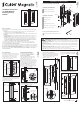
Component Drawings - Bi-Parting Mate
1
PAGE
PAGE
a
b
c
d
e
f
g
h
Bi-Parting Side Handle (Left)
a
b
c
d
e
f
(2)
g (6)
h (3)
Bi-Parting Side Handle Box
Bi-Parting Side Handle (Right)
Bi-Parting Face Plate
Bi-Parting Chassis Box
Bi-Parting Chassis
Magnet
Chassis Mounting Screws (2)
Side Handle to Chassis Screws (6)
Handle Face Plate Screws (3)
Door Preparation Fitting the Bi-Parting Mate Fitting the Bi-Parting Mate
3
PAGE
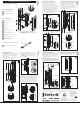
1. Mark a line on the face of the doors where
the centre of the handles are to be positioned.
Align the centre line on the door cut out
template with the centre line on the door.
Follow the instructions on the template.
Repeat cut out for both doors.
Door faceDoor face
Door cut out
template
Transfer
lines
across
front
edge of
doors
2. Mark two holes in the centre of the door
thickness in the positions shown. Using these
marks, drill two 2.5mm (3/32”) diameter holes
to a depth of 35mm (1-3/8”).
Repeat holes for both doors.
1
Chassis
mounting
screws
Centre of door
thickness
3
3. The Bi-Parting chassis contains a
strong magnet. Read the warning on
page 2 before continuing.
Remove the Bi-Parting chassis from its
packaging. Remove the face plate screw
and face plate from the chassis.
Align the chassis with the centre of the door
thickness. Screw the chassis to the door (using
the two chassis mounting screws) through
the slotted holes at the top and bottom of the
chassis. DO NOT fully tighten the screws.
Realign the chassis with the centre of the
door thickness. When happy with the chassis
position, fully tighten the screws.
3mm (1/8”)gap
under head
Side handle to
chassis screws
4
4. Fit the 6x side handle to chassis screws.
Leave a 3mm gap (1/8”) between the underside
of the screw head and the chassis.
Go to page 5 (overleaf)
Magnet
5. Fit one of the Bi-Parting side handles (left
OR right) to the chassis by sliding the front
flange of the handle under the heads of the
3x side handle to chassis screws.
Tighten the screws.
5
6
7
6. Fit the remaining Bi-Parting side handle
to the chassis and tighten the side handle
screws.
7. Fit the Bi-Parting face plate to the chassis
using the 3x handle face plate screws.
Handle
face
plate
screws
Bi-Parting
face plate
Before you Start:
1. These handles have been manufactured to specifications which cannot be altered by the installer.
These include:
a Handle type: the CL400 handle is available in Passage, Privacy, Key Locking and Bi-Parting
versions. You have purchased the Bi-Parting Privacy version.
b Configuration: the Privacy handle configurations include; Snib/Snib, Snib One Side and Snib/Emergency.
c Handing
d Door thickness range: the CL400 handle is available in three door thickness ranges. These are:
34-40mm, 40-46mm, 46-52mm and 52-58mm (1-3/8” to 1-9/16”, 1-5/8” to 1-3/4”, 1-13/16” to 2” and
2-1/16” to 2-1/4”).
e Security: the CL400 handle varies in security depending on the version and configuration.
The CL400 Bi-Parting Privacy configuration provides low level security. It is important to note
that the CL400 handle should not be installed in situations where a high level of security is
required, e.g. external entry points or high security internal doorways.
Refer to the information printed on the Side Handle and Chassis boxes to ensure you have
purchased handles with the correct specifications for your situation. If the specifications are
incorrect you will need to exchange the handles.
2. Component drawings have been provided. Please familiarise yourself with the components and check
the package to ensure nothing is missing. Note: Components may vary slightly between configurations.
3. To ensure the handles latch accurately, it is essential that the doors are adjusted for height and are parallel
with the closing jamb when closed before installing the handles.
4. The CL400 is a metric handle. Accurate measurements are shown in millimetres. Conversions to
inches are approximate.
Correct alignment
✓
==
Slotted
hole
Front flange
i
i
Tools (contained in Bi-Parting Chassis Box)
CL400 Allen Key (used for all machine screws)
WARNING: THE BI-PARTING CHASSIS CONTAINS A STRONG MAGNET
IRON FILINGS - Magnets will attract shavings from iron or ferrous metals which may be hard to
remove. Keep magnets a safe distance away from these materials.
DANGER FOR CHILDREN - Magnets may cause serious injury if swallowed. Keep out of reach of children.
CRUSHING, BLISTERS AND CUTS - Fingers may become caught between magnets resulting in crushing,
blisters or cuts.
BREAKING OR CHIPPING - It is possible that magnets could chip or shatter on contact, resulting in chips
flying off at high speed into someone’s eye. Chips can also be very sharp - treat them as you would broken
glass.
MAGNETICALLY SENSITIVE ITEMS - Keep a safe distance between the magnet and all objects that can
be damaged by magnetism (e.g. mechanical watches, pacemakers, cell phones etc.).
DISPOSAL - Magnets should be disposed of carefully and in accordance with your local regulations.
IMPORTANT: Install THIS handle FIRST
5mm
(13/64”)
5mm
(13/64”)
Ø 2.5mm
(3/32”)
2
Door
thickness