ETHERNET CAMERA, MPEG-4 ZN-L8000 INSTRUCTION MANUAL ZN-L8210PHA ZN-L8210NHA ZN-LN8048PHA ZN-LN8048NHA Color or Day/Night High Resolution Camera with Integrated Computar Auto-Iris Varifocal Lens & MPEG-4 Streaming Video 1
Copyright This manual is the intellectual property of CBC (America) Corp. All rights reserved. No part of this document may be reproduced or transmitted for any purpose, by any means, electronic or mechanical, without the express written permission of CBC (America) Corp. Edition: v2.0 - English April 2004 (based on CBC (Europe) Ltd. version 2.00) Note This manual was compiled with the greatest of care and all information has been double-checked for accuracy.
INDEX INDEX 3 INTRODUCTION 4 SAFETY INFORMATION 5 PRODUCT DESCRIPTION 6 INSTALLATION 8 CONFIGURATION WITH WEB BROWSER 11 OPERATION WITH INTERNET EXPLORER 26 SERVICE 27 TECHNICAL SPECIFICATIONS 28 3 v2.
INTRODUCTION This manual is intended for persons authorized to install and operate this camera and other VCS products. International, national and any relevant regional regulations relating to electronics must be observed at all times. Conventions In this manual, the following symbols and notations are used to draw attention to special situations: Attention! This symbol indicates tips and notes that make using the device easier and more convenient.
SAFETY INFORMATION Electrical Shock Hazard Ø Never attempt to connect the unit or the power supply to any power source other than the one for which it was provided for. Ø Use only appropriate and approved power supply units with this device (see technical specifications). Ø Do not open the housing of the power supply unit. Ø Disconnect the power supply unit from the outlet and from all other devices if a fault occurs.
PRODUCT DESCRIPTION System Requirements Ø PC with Windows 98/2000/XP operating system and network connection Ø Microsoft Internet Explorer web browser (version 5 and up) or serial interface and terminal program, e.g.
Multicast functions This camera utilizes MPEG-4 compression technology. Thanks to efficient encoding, the data transmission rate remains low, even with maximum image quality at 25 images per second; furthermore, it can be adapted to meet the bandwidth requirements of various network infrastructures. In appropriately configured networks, the multicast function permits the simultaneous video transmission in real time to several receivers.
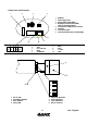
Connectors and Controls 1 8 3 4 1 2 3 4 5 6 7 8 USB Port Power Supply LED Analog Video Output (BNC) Day/Night Control Terminal (NO) (Only on Day/Night models) 10/100 Base-T LAN (RJ-45) connector Link LED Transmission LED Video termination switch (75 Ohm/High) 5 2 1 2 3 4 5 6 7 8 1 2 3 4 5 9 10 7 6 6 7 8 9 10 Line Audio In GND Line Audio Out GND ALARM IN 1 ALARM IN 2 Relay Relay 12 V DC GND 6 7 1 5/8 2 3 4 1 2 3 4 DC iris: ON Anti-Flicker: ON/OFF BLC: ON/OFF Always ON 5 6 7 8 8 VR for
INSTALLATION This camera is designed for indoor operations. Choose a site for installation which ensures that the camera is NOT exposed to extreme temperatures or extreme moisture or humidity. The ambient temperature must be between +40°F and 115°F (+5°C ~ 40°C) and the relative humidity cannot exceed 80%. During operation, the unit generates a good amount of heat. Please ensure sufficient ventilation and install this device away from heat-sensitive equipment or objects.
The relay output allows for switching external devices. This control output can be used interactively during an active connection with the camera. The contact can be programmed as normally open (NO) or normally closed (NC) and it is possible to invert the mechanical function by software setup. The relay contact must not be subjected to a load of more than 40V and 0.8A. Power Supply This camera has no master power switch.
CONFIGURATION WITH WEB BROWSER Making the Connection The integrated HTTP server offers you the possibility of configuring the camera over the network with a web browser. This possibility is far more convenient than the configuration via the terminal program and also allows you to view live video images. In order for live video images to be decoded, the special MPEG ActiveX control required must be installed on the computer.
Click on the items in the left gray bar to navigate the configuration pages. The pages are divided into categories; click on each category and then on the desired subject. To save your changes, it is necessary to click the Set button on each screen before moving on to another category of settings. Unit Identification ó General Settings Unit name: Enter a name for the camera to aid in identification in multiple camera systems.
Unit Identification ó Password Settings Password level: Access to the camera is generally protected with a password in order to prevent unauthorized use of the device. The transmitters operate with three authorization levels: Live, User and Service. Service - for configuration, services control and live picture. User - for services control and live picture. Live - for live picture only.
Unit Identification ó Time Server Settings The camera can receive a time signal from an NTP server and use it to set the internal clock. The device calls up the time signal automatically every two hours. Time zone: Time server IP address: select the current time zone. enter the IP address of the NTP server. Display Settings ó Camera name Camera 1: Enter here the camera name, click Set.
Video/Audio Settings ó MPEG-4 Encoder The data transmission parameters can be configured to suit the local operating environment (e.g. network architecture, bandwidth, data structures). The ZN-L8000 camera can provide you the power of 2 independent MPEG-4 Encoders that you can use at different transmission bandwidths, resolutions, etc. for remote transmission, local transmission or recording, in order to optimize your system and network usage.
Video resolution: You can choose between these resolutions: Low 176 x 144 pixels (QCIF) Standard 352 x 288 pixels (CIF) High 704 x 288 pixels (2CIF) Reset this parameter preset: When the 'Default' button is pressed, the parameters for the selected profile are reset to the factory default values. If the MPEG ActiveX control is not installed on your computer, a corresponding message will be displayed when you switch to the live image page.
Video loss alarm: Select the option On if the unit is to activate an alarm when the video signal is interrupted. Unified picture detection: This function constantly checks the contrast of the video image and triggers an alarm when the video is locked, for example, when the lens is covered. Motion alarm: Select On if the unit is to activate an alarm when the motion alarm is triggered. Alarm input 1/2: Select the option On in order to activate the alarm by means of an external alarm sensor.
Alarm IP address: You can enter the IP addresses of a possible receiver. Remote receiver password: Here you can enter the respective receiver password in case the receiver is protected by one. Live video auto-connect: Select the option On if it is required to re-establish a connection to the previously specified IP address after each restart, e.g. after a connection breakdown or network dropout. The addresses will be contacted in turn once until a connection is established.
Motion detector: Select the option On to activate the video sensor. Select sensor field: The areas of the image to be monitored by the video sensor are selected here. The video frame is subdivided into 396 square cells. Each of these cells can be activated or deactivated. If it is necessary to exclude particular regions of the camera field of view from the monitoring process because of, say, continuous movement (e.g.
Tracker: In the Tracker field you see an arrow, which indicates the current motion in the video image. By means of check boxes in the four corners, the desired direction can be activated. If, for example, all movements to the “left” and “upwards” are to activate an alarm, then mark the top left corner. If all movement to the “left”is to activate the alarm, then check the left upper and the lower left corners.
The following events can activate the relay: Ø Off: No relay triggering by events Ø Connection: Triggering if any connection is established Ø Video alarm: Triggering caused by loss of the video signal Ø Motion alarm: Triggering by the motion alarm Ø Local input: Triggering caused by an external alarm sensor Ø Remote input: Triggering by a switching contact from a remote location. Relay name: The relay can be assigned a name here. The name will be shown on the live page, depending upon the configuration.
DNS Server IP Address: When working with a device over the Internet, dynamic IP addresses are assigned for efficient use of the IP address pool, i.e. the device gets a new (changing) IP address each time a connection is set up. Connecting is easier when the device is listed on a DNS server. The device logs in regularly, leaving the device name, device IP address and the current Internet IP address.
The devices support the multi-unicast operation up to a maximum of 5 simultaneously connected receivers for MPEG-4. The transparent data connection is maintained from the first unit. However, after 15 seconds of inactivity the data connection is automatically suspended and another unit can exchange transparent data with the transmitter. For multilink operation, the network is not required to be multicast compatible as the devices are also multi-unicast compatible.
Service Settings ó Livepage Settings The live page can be set up to suit individual requirements. Options are provided here to display different information and operating elements along with the video picture. In addition, individual background images for the main window and for the upper screen area (banner) can be used. For the background image you can use the file types GIF and JPEG. The file paths must correspond to the type of access (for access to a locally stored file, for example, c:\Images\Logo.
Save general logfile to hard disk: Select this option to store the logfile in a text file on the local computer. File for saving alarm messages: Enter the path to the location where the log files for the alarm messages are stored. File for saving general messages: Enter the path to the location where the log files for the general system messages are to be stored.
OPERATION WITH INTERNET EXPLORER You must use Microsoft Internet Explorer from version 5, the Microsoft Java Virtual Machine and please disable the java script debugging. You need to install the MPEG ActiveX plugin. Your PC should support a video resolution of 1024 x 768 pixels. Connection Once you have configured your device, you may enter the IP address of the camera into the Internet Explorer address bar. (using 192.168.0.1 or http://192.168.0.1/ is acceptable.
Snapshot Individual images can be displayed in different resolutions. To select the resolution, append the corresponding parameter to the command snap.jpg: Ex: 192.168.0.1/snap.jpg Ø Snap.jpg?JpegSize=S 176 x 144 pixels Ø Snap.jpg?JpegSize=M 352 x 288 pixels Ø Snap.jpg?JpegSize=XL 704 x 576 pixels (default value) SERVICE The connection between two IP addresses can be checked using the command ping. You can thus check whether the device in the network is active.
TECHNICAL SPECIFICATIONS Video Model ZN-LN8048NHA System Sensor Pixels Scanning System Sync. System NTSC/EIA (Day/Night) ZN-LN8048PHA ZN-L8210PHA ZN-L8210NHA PAL/ CCIR (Day/Night) PAL NTSC 1/4" Interline Transfer CCD 768(H) x 492(V) pixels 752(H) x 582(V) pixels 768(H) x 492(V) pixels 2:1 interlaced Internal (H) : 15.734KHz (H) : 15.625KHz (H) : 15.734KHz (V) :59.94Hz (V) :50.00Hz (V) :59.94Hz 470 TVL 480 TVL 470 TVL >50dB < 0.09 lux (F1.6) @ 30 IRE (Night Mode) < 1.5 lux (F1.2) @ 50 IRE 0.45 1.
CBC (America) Corp. Imaging Technology Division New York Office Los Angeles Office 55 Mall Drive Commack, NY 11725 Tel.: 631 864 9700 Fax: 631 543 5426 20521 Earl Street Torrance, CA 90503 Tel: 310 793 1500 Fax: 310 793 1506 cctv@cbcamerica.com http://www.cbcamerica.com 29 v2.