T-Command Installation Guide Building Block Video Ltd., 17 Apex Park, Diplocks Industrial Estate, Hailsham, East Sussex, BN27 3JU UK. Tel: +44(0)1323 842727 Fax: +44(0)1323 842728 Support: +44(0)1323 444600 www.bbvcctv.
1. PRE-INSTALLATION CHECKS AND SAFETY PROCEDURES UNPACKING Check Packaging - Upon taking delivery of the unit, inspect the packaging for signs of damage. If damage has occurred, advise the carriers and/or the suppliers immediately. Check Contents - Upon taking delivery of the unit, unpack the unit carefully and check that all the items are present and correct. If any items are missing or damaged, contact your equipment dealer.
Damage Requiring Service - Servicing by qualified personnel should be carried out under the following conditions: (a) When the power-supply cord or plug is damaged. (b) If liquid has been spilled or objects have fallen into the unit (c) If the internal electronics of the unit have been exposed to rain or water (d) If the unit does not operate normally by following the operating instructions.
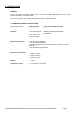
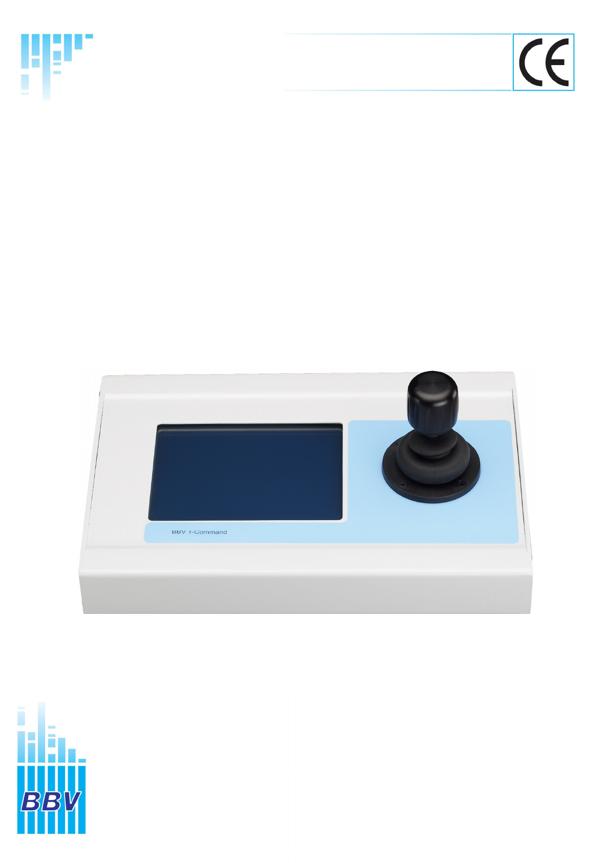
2. INTRODUCTION GENERAL The T-Command is designed to allow control of a variety of BBV Video Matrices, Pick A Point rd systems & a Variety of 3 Party DVRs. The T-Command is a user friendly keyboard with simple to understand icons. T-COMMAND TECHNICAL SPECIFICATION Power Requirements: 9VDC @ 500mA ( plug mounted PSU provided) Features: • 2 Serial data ports i RS232 or RS422/485 selectable. ii RS422/485 • 4.5” X 3.5” LCD. • 3 Axis Joystick. Engineering Facilities: • On site screen calibration.
3. INSTALLATION OPERATING VOLTAGE The T-Command requires 9VDC @ 500mA the LCD back light requires the full 9VDC to start. If the unit is supplied with less the keyboard will light and then fail. The T-Command can also be supplied with power by the CAT 5 cable fig 1. Fig. 1 Note the connections below are at the T-Command & the Tx would be Rx at the MATRIX / CPU end of the cable.
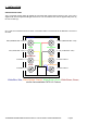
Fig. 2 Rear view of the T-Command Keypad. 4. DATA CONNECTIONS The T-Command has two serial data ports both support RS422. The 1st port is labelled as KEYBOARD this is dedicated for use with BBV equipment. The second is labelled as AUXILIARY this port is for further development and not defined in this manual. The T-Command is supplied with one CAT5 Patch Cable and one break out box. The Break out box enables the keypads to be installed over the site without cutting Patch cables. Fig.
Fig. 4 Internal view of the T-Command keypad.
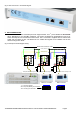
5. POWER UP SCREEN When the T-Command is powered up you will see the Boot up screen. This will give important configuration information. The Software Version will be very important when you call Tech Support +44 (0) 1323 444600. The Keyboard Type will depend on the application you are using the TCommand for. There are a number of options available. Menu access will be necessary to change the Keypad Type. 6. SETUP T-Command Keypad Configuration.
7. ENGINEERING MENU The Engineering Menu allows you to do a number of key things, Calibrate Joystick, Screen Calibration and select the Keypad Type. To navigate the menu you will need to use the joystick tilt up & down to move up & down then pan right to select. Calibrate Joystick - this will allow re-calibrating of the Joystick. You will go straight to a YES NO screen you will need to press the YES key to continue. Then you will need to follow the instructions that come up on the screen.
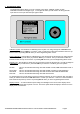
8. Tx1500 In this Keypad Type you will be able to control the BBV Tx1500; FBM Video Matrix & Pick A Point below is the main screen. On this screen you can carry out basic matrix functions ie Camera, Monitor, Preset selection & Pan, Tilt, Zoom Functions. To select a Monitor you will need to press a number pad ie 8 followed by MONITOR pad. This will select monitor 8 & it will update the 3 digit display next to the Mon legend. To select a camera you will need to press a number pad ie 6 followed by CAMERA pad.
If you press MENU you will move on to the next screen this gives more Matrix based controls. To start a sequence on the selected monitor you will need to press the SEQ pad. To acknowledge stacked alarms you will need to press the ALARM pad. To enter the Tx1500 menu you will need to press AND HOLD the PROGRAM pad. To enter the Tx1500 COAX menu you will need to press AND HOLD the # pad for 2 seconds. Cam 000 Mon 001 1 2 3 MENU 4 5 6 SEQ.
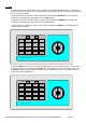
9. DX1 DIXONS In this Keypad Type you will be able to control the BBV Tx1500,when the matrix is set up in DIXONS MODE Ref, to BBV Tech Support +44 (0) 1323 444600. On this screen you can carry out basic matrix functions ie Camera, & Preset selection including Pan, Tilt, and Zoom Functions. To select a camera you will simply need to press a number pad ie 6, this will select camera 6, if you require cameras 13- 24 press the 13-24 pad.
Within the DX1 there is an Engineering Menu, to access this menu you will need to press AND HOLD the PRESET pad, This will then bring you to the PIN number screen. The Password is 2325. Calibrate Joystick - this will allow re-calibrating the Joystick. You will go straight to a YES NO screen you will need you press the YES key to continue. Then you will need to follow the instructions that come up on the screen. Or pressing NO will return you to the DX1 Engineering Menu screen.
To navigate the menu you will need to use the joystick tilt up & down to move up & down then pan right to select you will then be shown the YES NO screen to confirm your selection. Then the T-Command will re-boot and show the power up screen. Or pressing or pressing NO will return you to the DX1 Engineering Menu screen. Display Timeout – To reduce electrical power usage, the backlight for the touch screen display can be automatically turned off after a period of no use.
10 Ganz DVR Notes on using Touch Screen Keypad (V9 software) with GANZ ZR-DH1621NP The keypad connects to the DVR via the T-command keyboard port. The keypad only transmits since the DVR protocol at present does not provide any useful feedback data (i.e. status info etc.). Connections are as follows: Keypad Pin 3(+TX) Pin 6(-TX) DVR Pin 2(+RX) Pin 3(-RX) The keys that are displayed on the screen mainly mimic DVR front panel controls but some special keys control the keypad screens. Joystick.
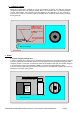
PTZ Screen. This screen is displayed after pressing the PTZ key. The PTZ toggle command is sent to the DVR. TOUR, AUTO, PTZ (toggle PTZ mode), IRIS, FOCUS keys mimic front panel although at present IRIS and FOCUS are not supported in the DVR protocol and do not function. CAMERA selects the Camera Select screen. PRESET selects the Preset screen but does not active the DVR OSD Preset menu. EXIT returns to the Main screen. Play Screen. This screen is displayed after pressing the PLAY key from another screen.
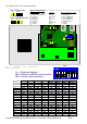
8 7 6 5 4 3 2 1 RJ45 GREEN RED BLUE YELLOW BLACK 1 2 NOT CONNECTED 3 BLACK 4 YELLOW 5 BLUE 6 RED 7 GREEN 8 Cable and RJ11 is a FARNELL subassembly. Part number: 754-948 NOT CONNECTED NOT CONNECTED TCOMMAND OPERATING INSTRUCTIONS V1.3 09-03-2009 V18 SOFTWARE.DOC NOT CONNECTED NOT CONNECTED BLACK YELLOW BLUE GREEN RED NOT CONNECTED WHITE IS NOT USED Fig. 6 interconnecting cable between T-Command keyboard port and Ganz DVR GANZ ZR-DH1621NP.
12 FAST DVR Connection between T-Command (keyboard port) and FAST DVR COM port. Note the T-Command port 1 will need to configured for RS232 refer to fig 4 page 7. T-Command RJ45 GREEN (4) BROWN PAIR (7 & 8) FAST DB9-F 2 (RXD) 5 (GND) Internal SW1 switch settings – ALL OFF. LIVE - PTZ CONTROL Cam 001 001 Mon IRIS+ FOCUS+ AUX1 IRIS- FOCUS+ AUX2 7 8 9 CAMERA MONITOR PRESET REPLAY BBV T Command LIVE MODE – ON POWER UP.
CHANGING CAMERA Press the CAMERA pad then using the numeric pads to select the camera required and then press the ENTER pad to select this new camera OR press the EXIT pad to keep with the original camera. Example CAMERA, 4, ENTER. This will select camera 4. CHANGING MONITOR Press the MONITOR pad then using the numeric pads to select the monitor required and then press the ENTER to select this new monitor or press the EXIT to keep with the original monitor. Example MONITOR 2, ENTER.
Other BBV products. Product Description camera desktop telemetry transmitter with BBV up-the-coax & TX300 Single 20mA telemetry, Pan/Tilt/Lens & Lights TX400 As TX300 inc Wash, Wipe, Autopan, 8 presets, preset patrol. TX400DC As TX400 including joystick for proportional Pan/Tilt control. 8 or 16 camera, 2 monitor telemetry transmitter. Up to 2 keyboards. up-the-coax and RS422 standard with options for alarm inputs and TX1000 MK2 BBV 20mA telemetry. Mid size matrix 16 – 96 camera, 8 monitor.