User’s Manual Version: 2.
Trademarks Copyright @2003 Contents are subject to change without notice. All trademarks belong to their respective proprietors. Copyright Statement THIS DOCUMENT CONTAINS OF PROPRIETARY TECHNICAL INFORMATION THAT IS THE PROPERTY OF THIS COMPANY. AND NO PART OF THIS DOCUMENTATION MAY BE REPRODUCED, STORED IN A RETRIEVAL SYSTEM OR TRANSMITTED IN ANY FORM OR BY ANY MEANS, ELECTRICAL OR MECHANICAL, BY PHOTOCOPYING, RECORDING, OR OTHERWISE, WITHOUT THE PRIOR WRITTEN CONSENT OF THIS COMPANY.
USER’S MANUAL OF WLAN ACCESS POINT Version: 2.1 Revision History DATE REVISION 2003/7/14 First release 2003/7/22 Release 1.1; add information about time required on boot-up sequence. 2003/7/24 Release 1.2; modify the boot-up sequence notice in chapter 1 2003/8/4 Release 2.0; add configuration examples 2003/9/9 Release 2.1; modify power supply to DC 7.
USER’S MANUAL OF WLAN ACCESS POINT Version: 2.
USER’S MANUAL OF WLAN ACCESS POINT Version: 2.1 Table of Contents REVISION HISTORY .....................................................................................................................I TERMINOLOGY ........................................................................................................................... II 1 INTRODUCTION.................................................................................................................... 1 1.1 1.2 1.3 1.4 1.
USER’S MANUAL OF WLAN ACCESS POINT 4.5 4.6 4.7 4.8 4.9 4.10 4.11 4.12 4.13 4.14 5 Version: 2.1 WHAT IS BSSID? .............................................................................................................. 20 WHAT IS ESSID? .............................................................................................................. 20 WHAT ARE POTENTIAL FACTORS THAT MAY CAUSES INTERFERENCE? ................................ 21 WHAT ARE THE OPEN SYSTEM AND SHARED KEY AUTHENTICATIONS? ......
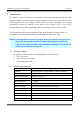
USER’S MANUAL OF WLAN ACCESS POINT Version: 2.1 1 Introduction The Wireless LAN Access Point is a portal that can act as the connection point between the Ethernet CSMA/CD protocol and the wireless CSMA/CA protocol. The Access Point can be easily integrated into your existing wireless network. In large installations, the roaming functionality provided by multiple Access Points allows wireless users to move freely throughout the facility while maintaining seamless, uninterrupted access to the network.
USER’S MANUAL OF WLAN ACCESS POINT Version: 2.1 Dimension 120 * 75 * 34 mm Operating Temperature 0 – 50oC ambient temperature Storage Temperature -20 - 70oC ambient temperature Humidity 5 to 90 % maximum (non-condensing) 1.3 Product Features Complies with IEEE 802.11b standard for 2.4GHz Wireless LAN. Supports 11Mbps data transfer rate with automatic fallback to 5.5M, 2M and 1Mbps. Supports bridging function between wireless and wired Ethernet interfaces.
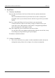
USER’S MANUAL OF WLAN ACCESS POINT Version: 2.1 Off 3. LAN LINK/ACT LED Flashing Off No data is transmitting or receiving on the antenna. Data is transmitting or receiving on the LAN interface. No connection is established on LAN interface. 1.5 Rear Panel Description Antenna Power Reset LAN Figure 2 – WLAN Access Point Rear Panel Interfaces Description 1. Reset Push continually the reset button 5 seconds to reset the configuration parameters to factory defaults. 2.
USER’S MANUAL OF WLAN ACCESS POINT Version: 2.1 2 Installation 2.1 Hardware Installation Step One: Place the Wireless LAN Access Point to the best optimum transmission location. The best transmission location for your WLAN Access Point is usually at the geographic center of your wireless network, with line of sign to all of your mobile stations. Step Two: Connect the Wireless LAN Access Point to your wired network.
USER’S MANUAL OF WLAN ACCESS POINT Version: 2.1 3 Software configuration There are web based management and configuration functions allowing you to have the jobs done easily. The Wireless LAN Access Point is delivered with the following factory default parameters. Default IP Address: 192.168.1.254 Default IP subnet mask: 255.255.255.0 WEB login User Name: WEB login Password: 3.1 Prepare your PC to configure the Wireless LAN Access Point For OS of Microsoft Windows 95/ 98/ Me: 1.
USER’S MANUAL OF WLAN ACCESS POINT 3. 4. 5. 6. 7. Version: 2.1 icon. Move mouse and double-click the Local Area Connection icon. The Local Area Connection window will appear. Click Properties button in the Local Area Connection window. Check the installed list of Network Components. If TCP/IP is not installed, click the Add button to install it; otherwise go to step 6. Select Protocol in the Network Component Type dialog box and click Add button.
USER’S MANUAL OF WLAN ACCESS POINT Version: 2.1 3.2 Connect to the Wireless LAN Access Point Open a WEB browser, i.e. Microsoft Internet Explore, then enter 192.168.1.254 on the URL to connect the Wireless LAN Access Point. 3.3 Management and configuration on the Wireless LAN Access Point 3.3.1 Status This page shows the current status and some basic settings of the device, includes system, wireless and TCP/IP configuration information.
USER’S MANUAL OF WLAN ACCESS POINT Version: 2.1 to join the same wireless network can identify it. Channel Number It shows the wireless channel connected currently. WEP It shows the status of WEP encryption function. Associated Clients It shows the number of connected clients (or stations, PCs). BSSID It shows the BSSID address of the WLAN Access Point. BSSID is a six-byte address. LAN configuration Attain IP Protocol It shows how the WLAN Access Point gets the IP address.
USER’S MANUAL OF WLAN ACCESS POINT Version: 2.1 Screenshot – Wireless Basic Settings Item Description Alias Name It is the alias name of this WLAN access point. The alias name can be 32 characters long. Disable Wireless LAN Tick on to disable the wireless LAN data transmission. Interface SSID It is the wireless network name. The SSID can be 32 bytes long. Channel Number Select the wireless communication channel from pull-down menu.
USER’S MANUAL OF WLAN ACCESS POINT Version: 2.1 knowledge about wireless LAN. These settings should not be changed unless you know what effect the changes will have on your Access Point. Screenshot – Wireless Advanced Settings Item Description Authentication Type Click to select the authentication type in Open System, Shared Key or Auto selection. Fragment Threshold Set the data packet fragmentation threshold, value can be written between 256 and 2346 bytes. Refer to 4.
USER’S MANUAL OF WLAN ACCESS POINT Version: 2.1 4.13 What is Preamble Type? Broadcast SSID Click to enable or disable the SSID broadcast function. Refer to 4.14 What is SSID Broadcast? Apply Changes Click the Apply Changes button to complete the new configuration setting. Reset Click the Reset button to abort change and recover the previous configuration setting. 3.3.4 Wireless Security Setup This page allows you setup the WEP security.
USER’S MANUAL OF WLAN ACCESS POINT Version: 2.1 bits) and secret key (40-bit or 104-bit). Key Format Select the WEP shared secret key format from pull-down menu. The format can be chose between plant text (ASCII) and hexadecimal (HEX) code. Default Tx Key Set the default secret key for WEP security function. Value can be chose between 1 and 4. Encryption Key 1 Secret key 1 of WEP security encryption function. Encryption Key 2 Secret key 2 of WEP security encryption function.
USER’S MANUAL OF WLAN ACCESS POINT Version: 2.1 Screenshot – Wireless Access Control Item Description Enable WEP Security Click the check box to enable wireless access control. This is a security control function; only those clients registered in the access control list can link to this WLAN Access Point. MAC Address Fill in the MAC address of client to register this WLAN Access Point access capability. Comment Fill in the comments for the registered client.
USER’S MANUAL OF WLAN ACCESS POINT Version: 2.1 previous configuration setting. 3.3.6 LAN Interface Setup This page is used to configure the parameters for local area network that connects to the LAN port of your Access Point. Here you may change the setting for IP address, subnet mask, DHCP, etc. Screenshot – LAN Interface Setup Item Description IP Address If the DHCP Client function is disabled, fill in the IP address of this WLAN Access Point.
USER’S MANUAL OF WLAN ACCESS POINT Version: 2.1 cloned. Clone MAC address is designed for your special application that request the clients to register to a server machine with one identified MAC address. Since that all the clients will communicate outside world through the WLAN Access Point, so have the cloned MAC address set on the wireless LAN access point will solve the issue. Apply Changes Click the Apply Changes button to complete the new configuration setting.
USER’S MANUAL OF WLAN ACCESS POINT Version: 2.1 Wireless LAN Received Packets It shows the statistic count of received packets on the wireless LAN interface. Ethernet LAN Sent Packets It shows the statistic count of sent packets on the Ethernet LAN interface. Ethernet LAN Received Packets It shows the statistic count of received packets on the Ethernet LAN interface. Refresh Click the refresh the statistic counters on the screen. 3.3.
USER’S MANUAL OF WLAN ACCESS POINT Version: 2.1 previous configuration setting. 3.3.9 Save /Reload Settings This page allows you save current settings to a file or reload the settings from the file that was saved previously. Besides, you could reset the current configuration to factory default. Screenshot – Save/Reload Settings Item Description Save Settings to File Click the Save button to download the configuration parameters to your personal computer.
USER’S MANUAL OF WLAN ACCESS POINT Version: 2.1 Screenshot – Password Setup Item Description User Name Fill in the user name for web management login control. New Password Fill in the password for web management login control. Confirmed Password Because the password input is invisible, so please fill in the password again for confirmation purpose. Apply Changes Clear the User Name and Password fields to empty, means to apply no web management login control.
USER’S MANUAL OF WLAN ACCESS POINT Version: 2.1 4 Frequently Asked Questions (FAQ) 4.1 What and how to find my PC’s IP and MAC address? IP address is the identifier for a computer or device on a TCP/IP network. Networks using the TCP/IP protocol route messages based on the IP address of the destination. The format of an IP address is a 32-bit numeric address written as four numbers separated by periods. Each number can be zero to 255. For example, 191.168.1.254 could be an IP address.
USER’S MANUAL OF WLAN ACCESS POINT Version: 2.1 to the wired LAN for services (file servers, printers, Internet links) they will operate in infrastructure mode. Example 1: wireless Infrastructure Mode Ad hoc mode (also called peer-to-peer mode or an Independent Basic Service Set, or IBSS) is simply a set of 802.11 wireless stations that communicate directly with one another without using an access point or any connection to a wired network.
USER’S MANUAL OF WLAN ACCESS POINT Version: 2.1 4.7 What are potential factors that may causes interference? Factors of interference: Obstacles: walls, ceilings, furniture… etc. Building Materials: metal door, aluminum studs. Electrical devices: microwaves, monitors and electrical motors. Solutions to overcome the interferences: Minimizing the number of walls and ceilings. Position the WLAN antenna for best reception.
USER’S MANUAL OF WLAN ACCESS POINT Version: 2.1 fragments each of size equal to fragment threshold. By tuning the fragment threshold value, we can get varying fragment sizes. The determination of an efficient fragment threshold is an important issue in this scheme. If the fragment threshold is small, the overlap part of the master and parallel transmissions is large. This means the spatial reuse ratio of parallel transmissions is high.
USER’S MANUAL OF WLAN ACCESS POINT Version: 2.1 stations to establish and maintain communications in an orderly fashion. Beacon Interval represents the amount of time between beacon transmissions. Before a station enters power save mode, the station needs the beacon interval to know when to wake up to receive the beacon (and learn whether there are buffered frames at the access point). 4.13 What is Preamble Type? There are two preamble types defined in IEEE 802.11 specification.
USER’S MANUAL OF WLAN ACCESS POINT Version: 2.1 5 Configuration Examples 5.1 Example One – DHCP on the LAN Sales division of Company ABC likes to establish a WLAN network to support mobile communication on sales’ Notebook PCs. MIS engineer collects information and plans the WLAN Access Point implementation by the following configuration. All the sales’ Notebook PCs will get IP address automatically from the DHCP server.
USER’S MANUAL OF WLAN ACCESS POINT Version: 2.1 Configure the LAN interface: Open LAN Interface Setup page and enable the DHCP Client function. Press button to confirm the configuration setting. Configure the WLAN interface: Open WLAN Interface Setup page, enter the SSID “SDWLAN”, Channel Number “1”. Press button to confirm the configuration setting.
USER’S MANUAL OF WLAN ACCESS POINT Version: 2.1 5.2 Example Two – Fixed IP on the LAN Company ABC likes to establish a WLAN network to support mobile communication on all employees’ Notebook PCs. MIS engineer collects information and plans the WLAN Access Point implementation by the following configuration. LAN configuration IP Address Subnet Mask Default Gateway WLAN configuration SSID Channel Number 192.168.1.254 255.255.255.0 192.168.1.10 MyWLAN 6 SSID: MyWLAN Channel: 6 IP: 192.168.1.
USER’S MANUAL OF WLAN ACCESS POINT Version: 2.1 Configure the LAN interface: Open LAN Interface Setup page, enter the IP Address “192.168.1.254”, Subnet Mask “255.255.255.0”, Default Gateway “192.168.1.10”. Press button to confirm the configuration setting. Configure the WLAN interface: Open WLAN Interface Setup page, enter the SSID “MyWLAN”, Channel Number “6”. Press button to confirm the configuration setting.
Federal Communication Commission Interference Statement This equipment has been tested and found to comply with the limits for a Class B digital device, pursuant to Part 15 of the FCC Rules. These limits are designed to provide reasonable protection against harmful interference in a residential installation. This equipment generates, uses and can radiate radio frequency energy and, if not installed and used in accordance with the instructions, may cause harmful interference to radio communications.