
User Manual


15
REPAIR & REPLACEMENT
1. After repairing any component:
a. check that electrical connections are correct and secure (see Figure 9),
b. remove any foreign material from enclosures,
c. install and secure all covers,
d. ensure that all fasteners are tight,
e. remove all foreign objects from heater, and
f. ensure air exits through louvers and fan rotates counterclockwise when
viewed from rear of heater (see Figure 14).
CORE
The heater core is vacuum charged and not field repairable.
For core removal:
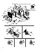
1. Remove cabinet bottom and element enclosure cover.
2. Disconnect all wires entering element enclosure (see Figure 10).
3. Slightly loosen all cabinet bolts shown in Figure 10, to prevent the core
from binding.
4. With an assistant supporting the weight of the core, remove the 3 core
mounting bolts. Carefully lower the core out of the cabinet
(see Figure 11).
5. To return core to factory, use crate supplied with exchange core to
protect the element terminals and plate threads.
6. To reinstall, lift the core up into cabinet while an assistant guides the
element wires into the element enclosure conduit.
7. Position the core and tighten the 3 core mounting bolts. Tighten the
remaining cabinet bolts.
TEMPERATURE HIGH-LIMIT
1. Remove temperature high-limit assembly and clean the inside of the
thermowell (see Figure 12). A clean thermowell will ensure good
thermal contact.
2. Use only a factory supplied temperature high-limit to ensure safe operation.
3. Apply a small drop, 3/32” (2mm) diameter, of heat sink compound to the
center of the metal cap but do not spread. This is critical for proper thermal
contact between the temperature high-limit and the thermowell (see
Figure
12).
4. Reinstall the temperature high-limit assembly with the snap ring and spring
into the thermowell without damaging the insulating tube. Secure in place
with the cotter pin (see Figure 13).
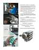
MOTOR, FAN & FAN GUARD
1. Remove bolts holding the motor to the motor mount. On units with a built
in thermostat, remove the bolts on the back of the thermostat enclosure.
2. Remove conduit #1 located between motor junction box and control
enclosure by turning it in the direction illustrated (see Figure 14).
Note conduits #1 and #2 are not interchangeable and have left hand
threads on one end, this end is indicated by a machined groove.
3. Remove the 2 piece fan guard assembly (see Figure 15).
4. Lift the motor assembly off the motor mount.
5. Before removing the fan, measure and record the location of the fan hub on
the motor shaft (see Figure 16). If difficult to remove, use a gear puller on
the fan hub.
6. To reassemble, place motor assembly onto motor mount and fasten the fan
guard to cabinet.
7. Simultaneously engage and tighten both ends of conduit #1 into
enclosures. Leave a 1/16” to 3/16” (1.6 to 4.8 mm) gap between the motor
and fan guard (see Figure 16). Adjust conduit #2 to center the fan in the
shroud.
8. To ensure a minimum 5 thread engagement, threaded ends of conduits
must protrude a minimum of 1/16” (1.6 mm) into enclosures. The groove on
conduit #2 must not be more than 7/8” (22 mm) from motor coupling
(see Figure 14).
9. Bolt motor to motor mount. Manually spin the fan blade to ensure fan
rotates freely.
10. Air must exit through louvers and fan must rotate counterclockwise
when viewed from rear of heater (see Figure 14).
FIGURE 14
FIGURE 11
Air inlet
Conduit #2
Conduit #1
7/8” (22 mm)
(From groove to
face of coupling)
WARNING
Disconnect heater from power supply at fuse box before opening enclosures
or servicing heater. Lock the switch in the “OFF” (open) position and/or tag the
switch to prevent unexpected power application.
Verify that power has been disconnected at fuse box or main panel. Lock
the switch in the “OFF” (open) position and/or tag the switch to prevent
unexpected power application. Heater surfaces may be hot.
Rotation
Remove
Install
Remove
Install
FIGURE 10
Loosen
bolts
only,
do not
remove.
Remove this
core mounting
bolt & two
others on the
opposite side.
Control
Enclosure
Conduit
Junction
Enclosure
{
}
Loosen
bolts
only,
do not
remove.
Element
Enclosure
FIGURE 13
FIGURE 12
Thermowell
3/32”
(2 mm)
Drop