Copyright This manual without the manufacturer's approved copy and reprinted partially or in full, or translated into another language is prohibited. Limitation of Liability This product is designed to prevent fire and theft is not the main means. We shall not be liable for accidents or damage by using this product can result in liability for accidents or damage In order to improve the performance of the product without prior notice to the product may be a firmware upgrade.
Content OVERVIEW 4 INSTALLATION 11 MONITORING 21 SYSTEM SETTING 30 RECORD SETTING 62 SEARCH 68 4 5 6 7 9 Safety Instruction Key Features What's included Rear Panel Remote Control At a Glance 11 15 16 Replacing HDD Basic Layout Connecting to an external device 23 Live Screen At a Glance 30 To move to the System Setup menu Camera Setting Display Setting Audio Setup User Setting Network Setup System Setting Storage Event Setup 31 37 42 43 45 48 52 54 62 63 68 68 69 To start the Record Se
Overview Safety Instruction The Company shall not have any responsibility for any accident or damage that may incur during the use of the product. For your safety, we provide a few instructions about installation, manipulation, cleaning, assembly/disassembly of the product as below. So please read carefully and comply with the instructions. Before installation Comply with the following instructions to prevent a fire, explosion, system failure or electric shock.
Key Features ~~ Up to 16 channels of 960H camera video can be displayed at 480 fps / 400 fps in real time ~~ Up to 16 channels of 960H camera videos can be saved at maximum 480 (NTSC) / 400 (PAL) fps. ~~ Simultaneous recording and playback of maximum 16 channels (at 120 fps @ 960H) ~~ Supports H.264 HP (High Profile) CODEC ~~ Auto alarm feature with self-diagnostics on the system (HDD S.M.A.R.T, system temperature, network error, FAN error, etc.
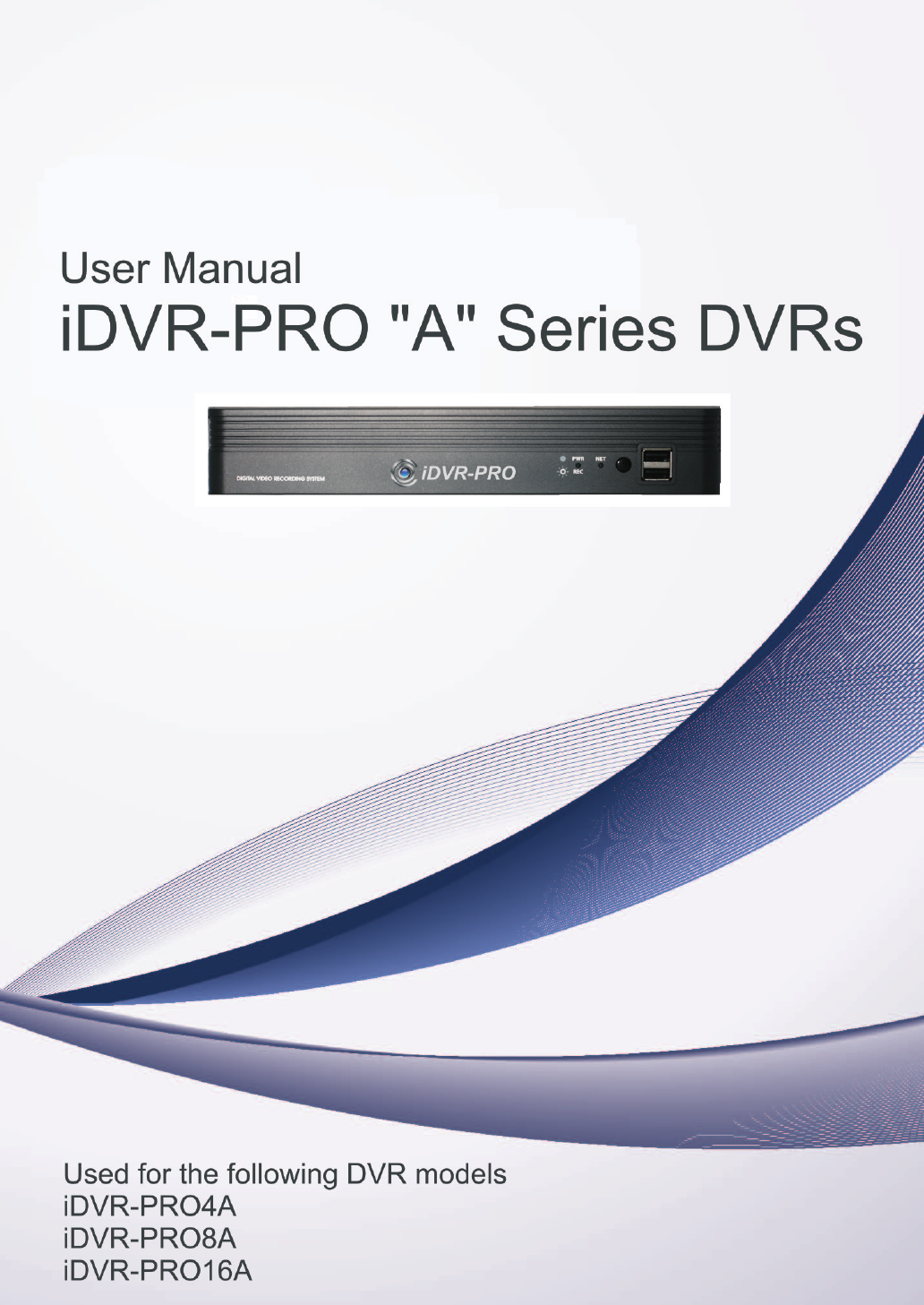
Overview What's included LOGOUT SEARCH ARCHIVE SETUP PANIC ALARM 1 2 4 5 7 8 9 +10 0 ID DISPLAY 3 6 SEQ LOG FREEZE KEYLOCK SNAPSHOT AUDIO PREV / NEXT EXIT RESERVE MENU ENTER W ZOOM PRESET T AF N FOCUS F ZOOM PTZ Mouse x1 Remote Control x1 & Batteries (AAA x2) Power Cable x1 DC 12V Adaptor x1 Screws Adapter cable retainer clip x1 User manual CD Quick Guide 6 | Overview
Rear Panel a VGA DC 12V 3 2 4 b ALARM IN 1/2 RELAY RS485 3/4 AUX VIDEO IN HD MONITOR ETHERNET f 1 IN 1 IN 2 GND IN 3 IN 4 NO COM NC D+ D- c Overview \\4 channels AUDIO IN i PAL AUDIO OUT NTSC d h e g \\8 channels a b c AUDIO IN 3 5 7 2 4 6 8 VIDEO IN VGA AUX ETHERNET 1/2 i RELAY RS485 DC 12V PAL AUDIO 3/4 OUT HD MONITOR ALARM IN IN 1 IN 2 GND IN 3 IN 4 NO COM NC D+ D- 1 d NTSC h g e f \\16 channels a b c AUDIO IN 3 5 7 9 11 13 15 2 4 6
Overview No. Name Description a VIDEO IN Video input terminal for cameras. b ETHERNET Network port for connection to the Internet, router or hub. c VGA VGA monitor video output port. d AUDIO IN 1/2 : Audio input terminal that supports channels 1 and 2. 3/4 : Audio input terminal that supports channels 3 and 4. ALARM IN Alarm input signal port. RELAY Relay Terminal output port. RS485 Ports for communication with external devices such as PTZ camera and system keyboard.
Remote Control At a Glance SEARCH Display the search window. ARCHIVE Display the backup window. Channel Function as channel selection button in live or playback mode. Or used for entering the password. DISPALY Switch the split mode. SEQ Switch to sequence mode. SNAPSHOT Take a snapshot of the video. LOGOUT SEARCH ARCHIVE SETUP 2 3 4 5 6 7 8 9 0 +10 SEQ DISPLAY SNAPSHOT ID LOG FREEZE KEYLOCK LOGOUT Log out. PANIC Start the emergency recording.
Overview \\Change the remote control ID The remote control will be active only if the remote control ID matches with that specified on the DVR. If multiple DVRs are installed on one place and you have just a single remote control, use the ID button to set the remote control ID. Only the ID-matching DVR can be controlled. 1. From - under the System Setup menu, set the and press . Select between 00 and 99. For more details, refer to .
Installation Replacing HDD Installation When an HDD is full or problematic, you can replace it with a new one by yourself. \\For 4-channel model 1. Remove the screw from the bracket on the bottom side of the DVR. the HDD bracket with your finger as shown in 2. Hold the figure and pull it to separate it from the DVR.
Installation the HDD on the bracket and fix it by fastening 3. Install 4 screws on its sides. When installing HDD, make sure to install in the correct direction. back the bracket installed with the HDD into 4. Insert the DVR. 5. Fix the bracket by fastening the screw.
\\For 8/16-channel models Remove the screw from each the bracket on the bottom side of the DVR. Installation 1. the HDD bracket with your finger as shown in 2. Hold the figure and pull it to separate it from the DVR. the HDD on the bracket and fix it by fastening 3. Install 4 screws on its sides. When installing HDD, make sure to install in the correct direction.
Installation back the bracket installed with the HDD into 4. Insert the DVR. 5. Fix the bracket by fastening the screw.
Basic Layout Installation IN AUX RNET 960H Camera Monitor IP Router or HUB AUDIO IN VGA ETHE ALAR M IN 1/2 HD MO NITOR AUDIO OUT PAL 3/4 RELAY RS485 IN 1 IN 2 GND IN 3 IN 4 NO COM NC D+ D- VIDEO DC 12 NTS C V Full HD (RGB) SPOT Monitor Monitor Speaker MIC Alarm Control Devices DC 12V Power Sensor JJ Since the cable quality may affect directly to the video quality depending on the distance between the camera and DVR, it is recommended to consult an authorized installer when i
Installation Connecting to an external device \\Connecting to the monitor 5 7 14 8 standard for proper operations. Setting9 the product to NTSC or PAL decides available display output modes too. 11 13 15 VGA 10 VIDEO IN 1/2 The monitor’s displaying operates at 50Hz if the product has been set to PAL output and the connected monitor supports both 50Hz and 60 Hz inputs. For NTSC setting, it works at AUDIO 3/4 12 60 Hz.
\\Alarm I/O Connection 10 VIDEO IN 13 4 12 14 5 7 6 8 15 16 9 11 13 15 10 12 14 16 VIDEO IN AUX ETHERNET AUDIO IN VGA AUX ETHERNET HD MONITOR VGA 1/2 HD MONITOR AUDIO 3/4 OUT AUDIO IN 1/2 PAL AUDIO 3/4 OUT ALARM IN IN RELAY RS485 ALARM RELAY RS485 IN 1 IN 2 GND IN 1 IN IN 32 GND IN IN 43 NOIN 4 NO COM COM NCNC D+ D+DD- 11 2 3 PAL DC 12V NTSC DC 12V NTSC To connect the alarm input signal Connect the signal line of an alarm input device such as sensor to the rear [
Installation \\Communication Port 11 2 10 VIDEO IN 3 13 4 12 5 7 6 8 14 15 16 9 11 13 15 10 12 14 16 VIDEO IN AUX ETHERNET AUDIO IN VGA AUX ETHERNET HD MONITOR VGA 1/2 HD MONITOR AUDIO 3/4 OUT AUDIO IN 1/2 PAL AUDIO 3/4 OUT ALARM IN IN RELAY RS485 ALARM RELAY RS485 IN 1 IN 2 GND IN 1 IN IN 32 GND IN IN 43 NOIN 4 NO COM COM NCNC D+ D+DD- 9 1 PAL NTSC DC 12V DC 12V NTSC RS-485 Connection Connect a PTZ Camera or Keyboard Controller.
\\Network Connection Installation PC connection in the local network You can connect DVR to a PC in the same network and control or manipulate it on the PC monitor. IN AUX AUDIO IN VGA ETH ALA RM 1/2 ERNE T HD MO NITOR AUDIO OUT PAL 3/4 IN REL AY RS4 IN 1 IN 2 GND IN 3 IN 4 NO COM NC D+ D- VIDEO 85 DC 12V NTS C Broadband router or hub Camera Local PC Local PC 1. Connect the [ETHERNET] port in the rear panel to the router or hub. 2. Connect the local PC to the router or hub.
Installation PC connection from a remote network You can connect DVR to a PC or mobile device in the same remote network and control or manipulate it on the monitor of the PC or mobile device. VIDEO IN AUDIO IN VGA AUX ETH ALA RM 1/2 ERNE T HD MO NITOR AUDIO OUT PAL 3/4 RS4 85 DC 12V Direct Connection Local PC Connect the [ETHERNET] port in the rear panel to the router.
Monitoring \\START 3. When the booting process is completed, the live screen then the login screen appears. \\Log In To manipulate or access the menus of DVR, you should have logged in. 1. When the system starts, the login screen appears. a user and provide the password. 2. Select The default password of the "ADMIN" account is "1234". . 3. Click If the login information is correct and valid, you will see the live screen.
Monitoring \\System Shutdown 1. In the monitoring screen, click
Live Screen At a Glance Video Window Quick Menu Timeline Status Bar \\Video Window Icons used in the video window. Item Camera ID Description Show the camera ID. Displayed if an event recording is reserved. Record Mode Icons Display the status of the continuous recording. Display the recording status when an alarm occurs. Display the recording status when a motion event occurs. Display the status of the emergency recording. Audio I/O Icons The audio signal of the connected camera is outputting.
Monitoring \\Status Bar Press the [▼] button on the remote control, or place the mouse in the lower area of the screen to display the status bar. Item Description Menu Button Select one of the system setup, search and backup menu items before accessing it. User ID Show the ID of the user who has currently logged in. Edit the screen layout to show the status bar and timeline at all times or only when the mouse cursor hovers on the status bar/timeline. Screen Control Buttons Select a split mode.
2014 2014 \\Timeline Item Timeline Date Description 2014 Expand/Collapse the timeline Navigation through Timeline Display the date of the current timeline. Click this to select a desired date of the timeline. Expand or collapse the timeline. 2014 Navigate through the timeline. You can also use the mouse wheel to do the navigation. Display the recording data with time.
Monitoring \\Using the status bar in the live mode Selecting a split mode Click a desired split mode from 1, 4, 9 and 16 split screen. Or press the [DISPLAY] button on the remote control until a desired split mode is displayed. Auto sequence Click the Sequence button in the status bar, or press the [SEQ] button on the remote control to perform the specified sequence mode. You can configure the sequence settings in . For details, refer to “Sequence”.
Digital Zooming You can enlarge the monitoring screen for better view. 1. Click Zoom in the status bar or move the cursor to a desired channel and right-click it to display the context menu. Select . You can also press the [ZOOM] button on the remote control. to the zoom control screen. When the menu 2. Move bar appears in the right bottom, use the buttons to control the zooming. i i : Select a channel to zoom in/out. : Zoom out the current (enlarged) image step by step.
Monitoring To select an audio input channel Select a channel from which the audio signal will be received. i CHANNEL : Produces the selected channel’s audio, regardless of the split screen mode. i LINK TO FULL SCREEN : When switching the DVR display mode to view one channel (Single Split), it produces the selected channel’s audio. A camera supports audio input should be used, and the DVR is connected to a speaker.
To check the disk status Monitoring You can check status and information on storage devices currently connected to the system. Click to close the window. For more information, refer to "Disk Information". (page 52) Saving captured snapshots You can capture the current video screen and save or export to a connected storage device. 1. Select a channel first, and right click to open popup menu, and select menu item, or press the [SNAPSHOT] button of the remote control.
System Setting To move to the System Setup menu ¯ How to use the mouse SEARCH ENTER ¯ How to use the remote control 1 MENU ¯ SETUP SEARCH MENU MENU ENTER ENTER ENTER How to use the remote control 2 SETUP 30 | System Setting ENTER ENTER SETUP ENTER
Camera Setting System Setting You can configure the display settings of: camera title, hidden option, motion and camera type. \\CAMERA TITLE You can change the camera ID that is displayed on the screen. 1. From - , select . the [▲▼◀▶/ENTER] buttons on the remote 2. Use control or use the mouse to select a channel that you want to rename. Alternatively, simply double-click the camera to rename from the top left corner.
System Setting \\Image Setup You can edit image settings and cropping settings for video from each camera. Color Setting You can adjust brightness, contrast, color and quality setting of each channel’s camera. (Not available for HD-SDI cameras.) 1. From - , select . [▲▼◀▶/ENTER] buttons of the remote control or 2. Use mouse to edit settings. 3. To apply your changes, click button. completed with setup, press [EXIT] button of 4.
\\Covert Setup 1. From - , select . the [▲▼◀▶/ENTER] buttons on the remote 2. Use control or use the mouse to select a covert channel(s) from a specific user group. i ADMIN, MANAGER, USER : Set them to . The selected channel will be covert from the applicable user account. i LOG OUT : Set it to . When the user logs out, the current channel will be set to a covert channel. apply the change, click in the bottom of 3. To the screen.
System Setting \\Motion Sensor Set the motion sensor of the camera so that it can detect a motion event. 1. From - , select . the [▲▼◀▶/ENTER] buttons on the remote 2. Use control or use the mouse to specify the use of each option item. i ACTIVATION : turn on or off the motion sensor. i MARK : Set to to display the motion detection indicator on each video tile where applicable.
the [EXIT] button on the remote control or 5. Press right-click any area to display the popup window as in the right picture. System Setting the popup window is displayed, select 6. While to set the motion detection sensitivity of the channel currently selected. i Channel: Select the channel to set the motion sensitivity. - SENSITIVITY : 1(Low) ~ 10(High) - The higher the number is, the more higher the sensitivity level becomes.
System Setting \\Enabling Privacy Mask For privacy purposes, you can specify masking area for a selected camera's video. 1. From - , select . [▲▼◀▶/ENTER] buttons of the remote or the 2. Use mouse to set channels enabled, mask color and its area. i ACTIVATION : Turns on or off the motion detection sensor in the specified privacy area. i MASK COLOR : Select the color of the masked area, which will be displayed on the monitor.
Display Setting System Setting You can configure screen display setup for On-screen Display, Sequence, and SPOT Out. \\OSD You can set Camera Name, Icon, Status Bar, Timeline, Borderline, User Name and Language. 1. From - , select . the [▲▼◀▶/ENTER] buttons on the remote 2. Use control or use the mouse to set each option of the OSD item. i CAMERA TITLE : specify the display of the camera title on the screen.
System Setting \\Monitor If you change from monitoring mode to sequence, you will have to set the interval of the sequence. 1. From - , select . the [▲▼◀▶/ENTER] button of the remote control 2. Use or mouse to set the dwell for Sequence mode and SPOT Out dwell. i SEQUENCE DWELL : Sets the time interval to the next screen mode for Live monitoring, which defines individual screen mode’s dwell time in the Sequence.
To add a sequence System Setting 1. Click in the bottom of the screen. the "ADD" dialog appears, enter a title using the 2. When virtual keyboard. 3. Enter the name of the sequence and click . the dialog appears, click 4. When . the "SEQUENCE SETUP" dialog appears, select 5. When a split mode that you want to add from . If the selected split mode is displayed on , select a channel you want to display in each split screen. 7. Click .
System Setting To edit a sequence 1. Select a sequence that you want to edit in the list. 2. The "EDIT" dialog appears. the [▲▼◀▶/ENTER] buttons on the remote 3. Use control or use the mouse to edit the selected sequence. i SEQUENCE TITLE : enter a new sequence name. i ACTIVATION : specify the use of the sequence. i MODIFY : change the settings of the sequence mode. i DELETE : delete the selected sequence list. i CANCEL : cancel the changes. 4.
\\SPOT OUT 1. From - , select . [▲▼◀▶/ENTER] button of the remote control or 2. Use mouse to edit Spot Out properties. i SPOT TITLE : Name the Spot Out setup. i ACTIVATION : Set whether to activate / deactivate the spot out setup. i MODIFY : Edit the view type of the spot output. i SAVE : Save the changes of spot output settings. To apply your changes, click button. 3.
System Setting Audio Setup You can configure audio related settings (channel and network transfer) and signal beep for remote control operations. \\Audio Choose whether to receive the live sound source and select an audio channel. 1. From -
User Setting System Setting You can configure the settings regarding user management and user and group permissions. \\Management You can add a user account(s) that can be edited at a later time. 1. From - , select . the [▲▼◀▶/ENTER] buttons on the remote 2. Use control or use the mouse to add a user account or select an item that you want to edit. apply the change, click in the bottom of 3. To the screen. done, press the [EXIT] button on the remote 4.
System Setting To edit the user account information 1. From the list of users, select a user account to edit and click next to it. the Edit window, make necessary changes and 2. From click . 3. To delete the user account, click . The account can not be changed or edited. \\Group Authority You can grant different user groups different permissions to a specific menu. 1. From - , select . the [▲▼◀▶/ENTER] buttons or use the mouse 2.
Network Setup System Setting You can set IP address, DDNS and E-mail settings, and check network status. \\IP Setup Edits IP address related properties and remote service port of the DVR. 1. From - , select . the [▲▼◀▶/ENTER] buttons on the remote 2. Use control or use the mouse to specify each item of the network settings. i DHCP : If it is checked, set the IP address of the DVR to Dynamic IP.
System Setting \\DDNS You can configure the DDNS settings so that remote users who are connected to the network can access remotely. DDNS is an IP redirection service in a dynamic IP environment that redirects (maps) the new IP address to a registered domain name each time the IP address is changed. - , select 1. From . the [▲▼◀▶/ENTER] buttons on the remote 2. Use control or use the mouse to specify the use of DDNS and select a server.
\\Network Status 1. From - , select . the [▲▼◀▶/ENTER] buttons on the remote control or use the mouse to select one between 2. Use and . done, press the [EXIT] button on the remote control or click in the lower screen. The confirmation 3. When message appears and you will return to the previous menu. Network Map i IP ADDRESS : Indicates the internal IP address of the DVR.
System Setting System Setting You can configure the settings of date/time, system management, and keyboard controller. \\Date/Time Specify the current date and time. 1. From - , select . the [▲▼◀▶/ENTER] buttons on the remote 2. Use control or use the mouse to change the time or set the options as necessary. i DATE/TIME : Set the current time and date. Click< > to adjust the time manually. i DATE FORMAT : specify the date format.
\\System Management You can check, update or reset the system information. From - , select . System Setting 1. the [▲▼◀▶/ENTER] buttons on the remote control 2. Use or use the mouse to set each option of the system management. i FW UPDATE : you can update the current software with the latest version. i FACTORY DEFAULT : Return the DVR settings to the factory default.
System Setting To perform the upgrade 1. Connect the USB storage device that contains the updatable files. 2. Click . one(s) from the updatable files listed in . 4. Click . 5. When the confirmation message appears, click . progress bar displays the progress of the 6. The firmware upgrade process. 7. When the upgrade is complete, reboot the system.
\\System Information You can check the current system version and system-related settings. From - , select . System Setting 1. 2. Check the status of the current system. done, press the [EXIT] button on the remote 3. When control or click in the lower screen to return to the previous menu. \\Control Device Configure the settings of the remote control and keyboard controller. 1.
System Setting Storage You can configure the settings of and view information of the disk. \\Disk Information It will show information about the connected disk. 1. From - , select . [▲▼◀▶/ENTER] buttons of the remote or the 2. Use mouse to check each connected peripherals. i START / END TIME : show the start time and end time of data stored in each disk. i STATUS : check if the connected disk is being used by the DVR.
\\Disk Operations 1. From - , select . the [▲▼◀▶/ENTER] buttons on the remote 2. Use control or use the mouse to set the operation conditions of the disk. i DISK WRITE MODE - If it is set to , the existing data will be overwritten by new recording data if the recording data size exceeds the free space of the HDD.
System Setting - NORMAL : The disk is in a normal state. - CHECK : The disk has an error so that you need to check the disk or the connection cables of the disk. If you leave the problem unresolved, no recording may be enabled. So it is recommended that you replace the disk immediately. - ERROR : The disk fails or is unable to use due to an error of the disk or the cable. The disk should be replaced immediately. Contact the retailer or the customer service to replace the disk. i S.M.A.R.
ON/OFF Schedule You can activate or turn off the alarm output as scheduled. Use the [▲▼◀▶/ENTER] buttons on the remote control or use the mouse to select a for the schedule. System Setting 1. the mouse to resize the cell or use the on the 2. Drag [▲▼◀▶] buttons to move to the cell, then press [ENTER]. 3. Select a desired alarm output mode. i ON : The alarm output is always turned on. i OFF : The alarm output is always turned off. i EVENT : Trigger the alarm output in sync with the event.
System Setting Buzzer output You can notify the user of the event using the buzzer. i DURATION - TRANSPARENT : Keep the buzzer out for as much time as the event lasts. - UNTIL KEY : Keep the buzzer out until a mouse or remote control button is pressed. - 5 ~ 300 SEC : Keep the buzzer out for as long as specified. Display If an event occurs, you can display the video screen or a popup message to notify the user of the event.
Email i ADD NEW EMAIL If you want to add a new mail recipient beside the existing ones, click this to add the recipient. i MINIMUM EMAIL FREQUENCY Adjust the minimum frequency of sending the email. For example, even if you have set the minimum frequency to one minute and another event occurs in less than one minute after the last email sending, the email for the new event will be sent one minute after.
System Setting \\Alarm Sensor You can configure the settings of the alarm sensor and specify the operation of the sensor if an event occurs. 1. From - , select . the [▲▼◀▶] buttons on the remote control or use the 2. Use mouse to specify the sensor input method and operation. i NAME : You can specify the name of the alarm sensor. i OPERATION : You can specify the type of the alarm sensor. - N/O (Normal Open) : Normally the sensor is left Open.
\\Motion Sensor 1. System Setting You can set an action to execute when a motion is detected. For the settings of the motion sensor, move to . From - , select . the [▲▼◀▶] buttons on the remote control or 2. Use use the mouse to specify the ignorance interval and operation. i IGNORING INTERVAL : Specify the minimum interval of the motion event occurrence.
System Setting \\System Event You can set any action to an event related to the disk, recording, network or system. Like the other events, you may notify the event to the user using the alarm/buzzer output, OSD pop-up or email. 1. From - , select . 2. Use the [▲▼◀▶] buttons on the remote control or use the mouse to specify the reaction to each event. 3. To apply the change, click in the bottom of the screen.
System i BOOTING EVENT: This event occurs when the System Setting DVR is booting. i LOGIN FAIL EVENT: This event occurs when the DVR fails to log in. You can specify the times of clicking < trigger the event. > to Network i TROUBLE IN INTERNET CONNECTION : Occurs if the Internet connection to the DVR fails. If you do not want to connect the DVR to the network, leave the item blank.
Record Setting You can configure the record settings for the DVR. Only authorized users can access the Record Setup menu.
Record Setup You can set the recording options for Auto or Manual mode. 1. From menu, select . the [▲▼◀▶] buttons or use the mouse to set to or . 3. Set the recording options for each selected Record mode. 4. To apply the change, click in the bottom of the screen. done, press the [EXIT] button on the remote control or click in the lower screen. The confirmation 5.
Record Setting \\Continuous Recording You can configure the settings of: continuous recording time, recording size, frame rate per second and quality. 1. From the menu, select . From , you must set to before you can set the . the [▲▼◀▶] buttons on the remote control or use the mouse to select either or 2. Use . Size/FPS/Quality Setting 1.
Schedule Setting Record Setting 1. Select a start day of the week on the schedule. a time cell from which you want to make the 2. Click schedule and drag it to a desired cell. Or use the [▲▼◀▶] buttons on the remote control to move to the cell and press [ENTER]. Then, use the [▲▼◀▶] buttons to move to a desired cell and press [ENTER] again. the time selection is complete, you will be 3. When prompted to specify the use of recording in the Record Setup window.
Record Setting \\Alarm Recording Specify the recording size of the alarm event if it occurs and make schedule for that recording. 1. From the menu, select the [▲▼◀▶] buttons on the remote control or use 2. Use the mouse to select either or . Set each item of , , 3. and use of the
\\Network Streaming You can specify the maximum size of network streaming for remote users and set the FPS. 1. Even if you set the resolution and FPS to high for the network streaming, the DVR will reduce the size or FPS according to the network status (speed) before transferring the recording video. From the menu, select . the [▲▼◀▶/ENTER] buttons on the remote 2. Use control or use the mouse to select an item that you want to edit.
Search You can search for the recording data in the HDD by the criteria of time, thumbnail, event, etc.
Search Settings Search \\Time Search With the calendar, you can search for the recording data by the recorded date. 1. From the menu, select
Search the [ENTER] button again on the remote control with the mouse, or simply double-click on the channel. 6. Press You will move to the playback screen. 7. If you want to stop playing and return to the search screen, press [EXIT] or [SEARCH] on the remote control. You can also click
\\Event Search Search for events that occurred at the specified time and select an event to play from the list. Search 1. From the menu, select . the [▲▼◀▶] buttons or use the mouse to specify 2. Use the and times in the left of the event search list. 3. Select a channel to search. the checkbox of the event to search from the 4. Mark list. the button. 5. Press The search results will be listed as shown. i TYPE : displays the event type.
Play If you want to play 1. To play the searched data You can search for and play a searched data. 2. To play with the live viewer - Simply double-click a desired time point in the right corner of the play screen. If you move the cursor to the rightmost, the "Timeline" bar will be displayed. - Select a desired channel in the live screen and right-click to select in the context menu. Then, select a desire play time.
Playback channel selection menu CAM1 Zoom Start bookmarking Snapshot Capture Description Display the title of the selected channel. Zoom the video of the selected channel. (The zooming function is active only in '1' split screen.) The "Set bookmark" popup appears, and you can bookmark a play point for the backup purpose. Capture the current live video and save it in the .jpeg format. Using the play bar Item Description Jump Move forward or backward.
Play Bookmarking During playback, you can add a bookmark for reserving the video data. You can view the bookmarked data in the Archive menu, which can be saved to a connected device for the backup purpose. 1. Provide a tag in the item for data reservation. the details of the reserved data in the 2. Provide input box. . 3. Click You will return to the play screen with the backup progress. 4. To stop the bookmarking, click . quit the bookmarking, click . 5.
Archiving To start the Archive menu Archiving Using the Archive menu during playback 1. During the playback, click . 2. The "ARCHIVING SETUP" window appears where you can reserve the data. 3. Click in the lower left corner and select the menu. 4. Press the [ARCHIVE] button on the remote control. Using the Archive menu during monitoring 1. Click in the lower left corner and select the menu. 2. Press the [ARCHIVE] button on the remote control.
Archiving \\Reserved data management You can search for the reserved data and delete or import it to a storage device. 1. From the menu, select . The reserved data will be listed. a data type from and . i AVI : Searches AVI video files stored in the DVR. i SNAPSHOT CAPTURE : Searches captured snapshots stored in the DVR. you want to play the data, double-click a desired 3. Ifdata item or click it and select .
\\Archive Devices Setup Provide the FTP server information for archiving data in the HDD before testing the transfer. From the menu, select . Archiving 1. 2. Move to the FTP information box. 3. Fill in each item using a virtual keyboard. i HOST NAME : enter the address at which you can access the server. i PORT : enter the port number to which you can access the server. i USER NAME : enter the user ID with which you can access the server.
Web Viewer What is the Web Viewer? Web RA is a user-friendly software application that enables you to control the video data in connection with a remote DVR. \\System Requirements The following is the minimum hardware and operating system requirements to run Web RA. Operating System Web browsers: CPU Memory Display Hard Disk Drive Windows XP Professional Windows Vista Home Baisc / Premium Window 7 Internet Explorer 7.0 or later/Mozilla Firefox 3.6/Google Chrome 4.
1. Provide the user ID and password. Web Viewer The default User name : ADMIN; the default Password is 1234. 2. Click the upper warning bar to install the ActiveX. If you fail to download the ActiveX control, move to Tools Internet Options Security Custom Level Download unsigned ActiveX control, and change its setting from “Disable (recommended)” to “Enable”, and then click OK. 3. Click . the installation is complete, you will see the live 4. When screen.
Web Viewer Live \\Live Screen At a Glance a b c h d g f e No. Item Description a View selection tab You can switch to the live, playback and setup screen and check the provided information. b Live Display the live screen of the currently connected DVR. c Split Mode Select and switch to a desired split-screen mode. d Sequence You can configure the sequence mode, view next camera, digital zoom and full screen. Status Show the connection status of each channel. Log Show the log.
Item Description f Voice transmission You can turn on or off the output of the voice signal. g Channel Select a channel listed in the screen. Save Save the live video on the screen. Print Print out the current screen. Capture Capture the selected image. ActiveX Settings Configure the ActiveX settings or specify the saving path of the captured image. h Web Viewer No.
Web Viewer \\To save the video 1. Click < > to start saving. 2. The video from the selected channel will be saved to the PC in the AVI format. (Default path: C:\SaveFolder) Click < > again to stop saving. Click to display the context menu where you can \\Print 1. Click < >. 2. The current screen will be printed with the printer connected to the PC. \\Screen capture 1. Click < >.
\\Status tab Web Viewer Click at the bottom of the screen. You can check the event occurrence for each channel of the connected DVR. \\Log tab Click at the bottom of the screen. You can check the log of the connected DVR. \\PTZ tab Click at the bottom of the screen. You can control the operations of a PTZ camera. Adjust the focus, zooming and iris of the camera. You can use the arrow buttons to control the operations of the camera.
Web Viewer Search Click to display the remote control screen for the DVR. \\Search Viewer at a Glance a b c d e f j i h g No. Item Description a View selection tab You can switch to the live, playback and setup screen and check the provided information. b Playback Screen Play the recording data. c Split Mode Select and switch to a desired split-screen mode. d Sequence Set the sequence mode, switch to the next camera, zoom the screen or select the full screen mode.
No. i j Description REFRESH Reload the time line. PLAY Play the video that satisfies your search criteria. Backup Archive the video that satisfies your search criteria. Channel Selection Select a channel listed in the screen. Screen Print out the current screen. Image Capture Capture the selected image. ActiveX Settings Configure the ActiveX settings or specify the saving path of the captured image.
Web Viewer Setup Click to display the remote control screen for the DVR. When done, click to apply the changes to the remotely connected DVR. If the DVR is in process of system or record setting, the remote control will be disabled. JJ If you change the settings remotely at will, the major 'Record Settings' of the DVR may be changed, which is not recommended at all.
Covert Setting Web Viewer You can set to hide the video of a specific camera from a specific user. Set to hide the camera video so that a specific user or user group can not view. To change the covert settings from user group to user, move to the menu and make necessary changes. When done, click to apply the changes. Motion Setting Specify the use of motion detection and reaction for each channel and set also the daytime/nighttime options. Select a channel.
Web Viewer PTZ setting To make DVR utilize camera’s PTZ functions, match the protocol and baud rate of connected cameras and DVR. Privacy Mask You can enable a camera channel’s privacy masking area and its mask color.
\\Display Web Viewer OSD Setting Configure the settings for the time, title, boundary, icon and language that will be displayed on the screen. Make changes to each item of the OSD menu and click to apply the changes. For details about each displayed item, refer to "OSD". (page 37) Monitor Settings You can set the interval of an active sequence. Specify the interval and click to apply it. i SEQUENCE DWELL : Switching time from one channel to the next channel in single screen mode.
Web Viewer \\User User Management You can add a user account and change the password. For details about each displayed item, refer to "User Setting". (page 43) To add a user, click and provide the user information. If you want to delete the user click next to it. When done, click to apply the change. Group Permission Setting You can grant different user groups different permissions to a specific menu. Mark the checkboxes of the menu items accessible by the user group.
\\Network Web Viewer Network Setting You can check the network connection status and change the baud rate. Change the maximum transfer rate and click to apply it. For more information about each network entry, refer to "IP Setup". (page 45) DDNS Setting You can configure the DDNS settings so that remote users who are connected to the network can access remotely. Change the DDNS settings and click to apply the changes.
Web Viewer \\System Date/Time Setting Specify the current date and time. When done, click to apply the changes. For more information about each of the time and date settings, refer to "Date/Time". (page 48) System Management You can configure the access settings of: log in, log out, and auto logout. System Information You can check information of system firmware version, disk space, and network settings, as well as the status information of network connection and alarm I/O.
Control Device Setting Web Viewer Set the connection of both the remote control and the keyboard control. Change the communication settings and click to apply the changes. For more information about each communication item, refer to "Control Device". (page 51) \\Storage Device Information Internal storage devices physically installed in the DVR and their recording time information are displayed.
Web Viewer \\Event Alarm Output Specify the alarm output conditions with the work schedule. When done, click to apply the changes. For more information about the alarm output and ON/OFF schedule, refer to "Alarm Out". (page 54) Event Notification You can set desired event actions triggered by an event, such as , , and notifications.
Alarm Sensor Web Viewer You can configure the settings of the alarm sensor and specify the operation of the sensor if an event occurs. When done, click to apply the changes. For more information about each of the alarm sensor actions, refer to "Alarm Sensor". (page 58) Motion Sensor You can set an action to execute when a motion is detected. When done, click to apply the changes. For more information about how to set the motion sensor, refer to "Motion Sensor".
Web Viewer System Event You can set event actions for disk, recording, network and system events. As same to setting event actions for normal events, you can set to trigger alarm output, buzzer, display on-screen pop-up, or send event notification via email and FTP. When done, click to apply the changes. For more information about how to set the system event, refer to "System Event".
\\Record Setup Web Viewer Operation mode You can set the recording options for AUTO CONFIGURATION or MANUAL CONFIGURATION mode. When done, click to apply the changes. For more information about how to set each mode, refer to "Operation Mode".
Web Viewer Continuous Recording You can configure the settings of: continuous recording time, recording size, frame rate per second and quality. Click < > next to each item to display the list of values available. When you complete the recording size and schedule settings, click to apply your settings. For more information about the continuous recording size and schedule, refer to "Continuous Recording".
Motion Recording Web Viewer Set the and the to apply if a motion event occurs. Click < > next to each item to display the list of values available. Complete setting the for the motion recording as well as the , and click to apply the changes. For more information about the motion recording size and schedule, refer to "Motion Recording".
Web Viewer Alarm Recording Set the and the to apply if an alarm event occurs. Click < > next to each item to display the list of values available. Complete setting the for the alarm recording as well as the , and click to apply the changes. For more information about the alarm recording size and schedule, refer to "Alarm Recording".
Network Streaming Web Viewer You can specify the maximum size of network streaming and video resolution for remote users and change the FPS. > next to each item to display the list of values Click < available. When done, click to apply the settings. Setting the Audio Mapping You can activate audio of a channel to communicate to the remote user. > on the right side of each item to display audio Click < channels available to select. Click to complete and apply audio setup.
Mobile Viewer nViewer You can use the smart viewer to monitor the network on a remote site and play the monitoring video anytime anywhere. \\nViewer specification Minimum / recommended specification OS Android Phone Minimum specification Recommended specification Flash : 512 MB or higher Flash : 512 MB Processor :800 MHz or higher RAM : 512 MB or higher SD Card : 4 GB or higher OS : 2.0 or higher iPhone 102 | Mobile Viewer iPhone 3G iPod touch 3rd Generation iPhone OS 3.1.
\\Using the nViewer on iPhone From your iPhone, access the App Store. Enter "nViewer" in the search bar to find it before downloading. Install the application on your iPhone. The nViewer supports the multi split screen mode. JJ The nViewer Lite is a free application, and does not provide search, log view, PTZ control and system configuration functions. To connect to DVR with nViewer 1. Select and run the nViewer. < > in the top right corner of the DVR List to 2.
Mobile Viewer the IP address, HTTP port number and 4. Provide RTSP port number, and click . the access ID of the DVR as well as the 5. Provide password. 6. Specify the use of the Auto Login. 7. Click . 8. Select the site that you added in the DVR List.
9. Try to access the DVR. If connected successfully, you will see the screen as shown. Mobile Viewer Split Mode 1. Click any area on the screen. The main menu appears at the bottom of the screen. PTZ ZOOM HD/HQ PTZ < > in the top left corner to switch to 1-split 2. Click > to switch to Multi-split mode. mode; click < PTZ ZOOM PTZ PTZ ZOOM ZOOM ZOOM HD/HQ HD/HQ Use the finger to scroll the screen to the left or right to move to the next camera video screen.
Mobile Viewer To use PTZ control 1. Click < > in the top right corner. buttons on the screen for PTZ control. (available 2. Use only for cameras supporting PTZ functions.) PTZ PTZ : CAM1 Done ZOOM Position Step HD/HQ 5 Position Step : Adjusts focus. : Click the button to 5 Position Step Position Step 5 . Position Step 1 1 Position Step Position Step 1 1 : Select one from the listed presets to run the selected preset action stored in the camera.
Using the Log View 1. Mobile Viewer From the main menu, click < >. You can check the log of the data stored. one from Alarm, Motion, Record, Etc. and 2. Select >. click < You will view the log of related items.
Mobile Viewer Using the Search function 1. From the main menu, click < >. You can view the history of the data stored. a desired time and date. 2. Select You can use the vertical time bar to specify the start time. < > to play the video recorded at the 3. Click specified time. any area to display the play bar with which you 4. Click can control the playing direction and speed of the Time Line Playback : CAM1 Live View video.
Using the Setup function Mobile Viewer From the main menu, click < >. You will be connected to the web viewer site. For details about each displayed item, refer to "Setup".
Mobile Viewer \\Using nViewer with Android How to download the Android-dedicated application From your smart phone, access the Play Store. Enter "nViewer" in the search bar to find it before downloading. Install the application on your Smart Phone. The nViewer supports the multi split screen mode. JJ The nViewer Lite is a free application, and does not provide search, log view, PTZ control and system configuration functions. To connect to DVR with nViewer 1. Select and run the nViewer. 2.
the site that you added in the DVR List. 8. Select Press and hold the mouse button to display the pop-up window. Mobile Viewer 9. Select and try to access. If connected successfully, you will see the screen as shown.
Mobile Viewer Split Mode 1. Click any area on the screen. The main menu appears at the bottom of the screen. PTZ ZOOM HD/HQ PTZ < > in the top left corner to switch to 1-split 2. Click > to switch to Multi-split mode. mode; click < PTZ ZOOM PTZ PTZ ZOOM ZOOM ZOOM HD/HQ HD/HQ Use the finger to scroll the screen to the left or right to move to the next camera video screen.
To use PTZ control PTZ PTZ Mode Back Position Step ZOOM 1 HD/HQ Position Step : Adjusts focus. : Click the button to 1 Position Step . 1 Position Step 1 Position Step 1 Position Step Position Step 1 1 : Select one from the listed presets to run the selected preset action stored in the camera. Position Step 1 Position Step 1 : Activates Pan / Tilt toward the selected direction. : Captures the real-time video and saves as a still image in the handset’s image folder.
Mobile Viewer Using the Log View 1. From the main menu, click < >. You can check the log of the data stored. one from Alarm, Motion, Record, Etc. and 2. Select click < >. You will view the log of related items.
Using the Search function 1. Mobile Viewer From the main menu, click < >. You can view the video of the recording data. a desired time and date. 2. Select You can use the vertical time bar to specify the start time. < > to play the video recorded at the 3. Click specified time. any area to display the play bar with which you 4. Click can control the playing direction and speed of the Back Playback Mode Live View video.
Mobile Viewer Using the Setup function From the main menu, click < >. You will be connected to the web viewer site. For details about each displayed item, refer to "Setup".
Archive Viewer You can play the data archived in the DVR. You can play the HDD data recorded by the DVR. Getting started with the Backup Player Archive Viewer 1. Connect the DVR to the backup USB storage device. 2. Open the folder saving the archived images. 3. Run the Backup Player. < > in the bottom left corner to display the 4. Click file browser. Select the archived file to play.
Archive Viewer 5. Check the integrity of the archived file. done, the archived file will be played on the 6. When screen.
Backup Player At a Glance a Archive Viewer b c d i h e No. f g Item Description Setup Configure the environment settings. Minimize, Close Minimize or close the Backup Player. b Channel Information Show the channel information and the video resolution. c Play Time Display the time of the current video image. d Play Time Display the current playback time. File Search Open the file that you backed up. Capture Capture the current screen. Print Print out the current screen.
Archive Viewer \\Video Capture Click < > to capture the current video image. i Selected Video : Capture the actual frame of the current video. i Screen : Capture the visible portion of the current video. i Format : Select a saving format.(BMP, JPG, PNG) i Path : Specify the saving path. - Default location : My Documents\My Pictures \\Print Out Click < > Button to print out the image. When the "Print" window appears, check the preview and click .
\\Settings Archive Viewer Click < > to configure the Backup Player settings. You can check the version of the Backup Player. i Maintain image aspect ratio : Preserve the aspect ratio of the image. If you do not mark this option, the image will be adjusted to fit the screen. i I frame Play : Only the I frames (key frames) will be playback. i About : You can check the program information including the current version.
Appendix Specification Item VIDEO AUDIO RECORDING ALRM I/O STORAGE 122 | Appendix 4CH 8CH 16CH INPUT SIGNAL NTSC/PAL NTSC/PAL NTSC/PAL MAIN MONITOR HDMI / VGA HDMI / VGA HDMI / VGA SPOT OUT Analog 1CH(1Vpp, 75Ohm) x1 Digital 1CH/4CH (1Vpp, 75Ohm) x1 Digital 1CH/4CH (1Vpp, 75Ohm) x1 LOOP THROUGH NO NO NO MOTION DETECTION YES YES YES INPUT SIGNAL 4CH(10KOhm, 2.8Vpp) 4CH(10KOhm, 1Vrms) 4CH(10KOhm, 1Vrms) OUTPUT SIGNAL 1CH(600Ohm, 2.
Item ETC POWER ENVIRONMENT CHASSIS CERTIFICATION 8CH 16CH USB 2 front 2 front 2 front RS-485 1 1 1 RS-232 NO NO NO LAN 1x 10/100 1x 10/100/1000 1x 10/100/1000 REMOTE CONTROL YES YES YES SIGNAL SWITCH NO YES YES WATCHDOG YES YES YES COOLING FAN NO 1x 40mm 1x 40mm POWER SUPPLY DC12V, Adaptor, 3.3A, 100~240V AC, 50-60Hz DC12V, Adaptor, 3.3A, 100~240V AC, 50-60Hz DC12V, Adaptor, 3.
Appendix Compatible HDD Specifications ~~ SATA1(1.5G) : Can be used ~~ SATA2(3.0G) : Can be used Maximum SATA Speed ~~ SATA3(6.0G) : Devices of backward compatibility to SATA2 (3.0G) can be used. Maximum Start-up Current 12V, 2A (or lower) Maximum Average Operation Power Consumption 7W (or lower) Maximum R/W Latency Latency (Read: 13ms / Write: 13ms) or smaller 124 | Appendix Use 3.5” HDD disks. Using HDD devices other than recommended specifications may cause serious problem.
Troubleshooting (FAQ) The system does not operate at all with no active LED in the front panel. Action ~~ Make sure that the system gets supplied with power properly. ~~ Check the input voltage. ~~ Check if the system fan in a side panel of the unit or the CPU fan inside The unit continuously reboots. the unit works properly. If it fails, contact the retailer or the service center. ~~ Disconnect the HDD cable and try to boot the system again.
Open Source License Report on the Product The software included in this product contains copyrighted software that is licensed under the GPL/LGPL. ~~ GPL Software : linux kernel, busybox, cdrtools, dvd+rw-tools, smartctl, uboot, bash, udev, sysklogd ~~ LGPL Software : glibc, vmstat, glib, gtk, libESMTP, iconv, gstreamer, pango, ~~ OpenSSL License : OpenSSL GNU GENERAL PUBLIC LICENSE Version 2, June 1991 Copyright (C) 1989, 1991 Free Software Foundation, Inc.
c) Accompany it with the information you received as to the offer to distribute corresponding source code. (This alternative is allowed only for noncommercial distribution and only if you received the program in object code or executable form with such an offer, in accord with Subsection b above.) The source code for a work means the preferred form of the work for making modifications to it.
Also add information on how to contact you by electronic and paper mail. If the program is interactive, make it output a short notice like this when it starts in an interactive mode: Gnomovision version 69, Copyright (C) year name of author Gnomovision comes with ABSOLUTELY NO WARRANTY; for details type ‘show w’. This is free software, and you are welcome to redistribute it under certain conditions; type ‘show c’ for details.
A “Standard Interface” means an interface that either is an official standard defined by a recognized standards body, or, in the case of interfaces specified for a particular programming language, one that is widely used among developers working in that language.
d) Convey the object code by offering access from a designated place (gratis or for a charge), and offer equivalent access to the Corresponding Source in the same way through the same place at no further charge. You need not require recipients to copy the Corresponding Source along with the object code.
9. Acceptance Not Required for Having Copies. You are not required to accept this License in order to receive or run a copy of the Program. Ancillary propagation of a covered work occurring solely as a consequence of using peer-to-peer transmission to receive a copy likewise does not require acceptance. However, nothing other than this License grants you permission to propagate or modify any covered work. These actions infringe copyright if you do not accept this License.
15. Disclaimer of Warranty. THERE IS NO WARRANTY FOR THE PROGRAM, TO THE EXTENT PERMITTED BY APPLICABLE LAW. EXCEPT WHEN OTHERWISE STATED IN WRITING THE COPYRIGHT HOLDERS AND/OR OTHER PARTIES PROVIDE THE PROGRAM “AS IS” WITHOUT WARRANTY OF ANY KIND, EITHER EXPRESSED OR IMPLIED, INCLUDING, BUT NOT LIMITED TO, THE IMPLIED WARRANTIES OF MERCHANTABILITY AND FITNESS FOR A PARTICULAR PURPOSE. THE ENTIRE RISK AS TO THE QUALITY AND PERFORMANCE OF THE PROGRAM IS WITH YOU.
The “Library”, below, refers to any such software library or work which has been distributed under these terms. A “work based on the Library” means either the Library or any derivative work under copyright law: that is to say, a work containing the Library or a portion of it, either verbatim or with modifications and/or translated straightforwardly into another language. (Hereinafter, translation is included without limitation in the term “modification”.
b) Use a suitable shared library mechanism for linking with the Library. A suitable mechanism is one that (1) uses at run time a copy of the library already present on the user’s computer system, rather than copying library functions into the executable, and (2) will operate properly with a modified version of the library, if the user installs one, as long as the modified version is interface-compatible with the version that the work was made with.
END OF TERMS AND CONDITIONS How to Apply These Terms to Your New Libraries If you develop a new library, and you want it to be of the greatest possible use to the public, we recommend making it free software that everyone can redistribute and change. You can do so by permitting redistribution under these terms (or, alternatively, under the terms of the ordinary General Public License). To apply these terms, attach the following notices to the library.
MM28AU01