
Manual

English
|
17
Installation
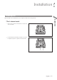
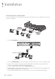
Alarm I/O Connection
To connect the alarm input signal
Connect the signal line of an alarm input device such as sensor to the rear [ALARM IN] port.
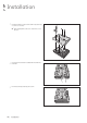
1.
Push the Alarm In and [GND] terminals
’
bottom side with a sharp tipped tool such as screw driver.
2.
While pushing, insert one end of alarm signal cable into the hole of Alarm In terminal.
3.
While pushing, insert one end of ground cable into the hole of [GND] terminal.
4.
To check proper insertion of cable, stop pushing and gently pull the cable and test whether it disconnects.
To disconnect a cable, push the bottom side of the terminal and pull out the cable.
To connect the alarm output signal
Connect the signal cable of the alarm output device to the [RELAY] terminal on the product
’
s rear side.
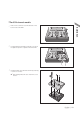
1.
Push the [NO]/[NC]/[COM] terminal
’
s bottom side with a sharp tipped tool such as screw driver.
2.
While pushing, insert one end of alarm signal cable into the desired terminal of [NO] or [NC].
NO(Normal Open) : Normally Open but switching to Close if an alarm out occurs.
COM : Insert the grounding wire.
NC(Normal Close) : Normally Close but switching to Open if an alarm out occurs.
3.
Insert the ground signal wire into the hole of the [COM] port (shown also below the screw), and tighten the screw.
4.
To check proper insertion of cable, stop pushing and gently pull the cable and test whether it disconnects.
To disconnect a cable, push the bottom side of the terminal and pull out the cable.
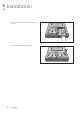
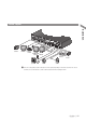
HD MONITOR
VGA
AUX
DC 12V
ETHERNET
VIDEO IN
IN 1
IN 2
GND
IN 3
IN 4
NO
COM
NC
D+
D-
ALARM IN RELAY RS485
PAL
NTSC
3
1
7
5
11
9
15
13
4
2
8
6
12
10
16
14
AUDIO
IN
AUDIO
OUT
1/2
3/4
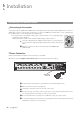
HD MONITOR
VGA
AUX
DC 12V
ETHERNET
VIDEO IN
IN 1
IN 2
GND
IN 3
IN 4
NO
COM
NC
D+
D-
ALARM IN RELAY RS485
PAL
NTSC
11
9
15
13
12
10
16
14
AUDIO
IN
AUDIO
OUT
1/2
3/4