Keyboard Controller User Manual 1
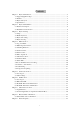
Contents Chapter 1 Keyboard Instruction ..................................................................................................... 2 1.1 Support Equipments Type ................................................................................................... 2 1.2 Features ............................................................................................................................... 2 1.3 Keyboard Layout ...........................................................................
Chapter 1 Keyboard Instruction Intelligent Network Keyboard is the controller device of surveillance system launched by our company. It supports Chinese/English operation interface and Chinese/English WEB setup interface, and can control many kinds of analog/digital surveillance equipments. 1.1 Support Equipments Type Intelligent Network Switch Speed Dome/Decoder PC Based DVR Standalone DVR Network Video Server Management Host Digital Video General Platform Screen Splicing Controller 1.
Area A LCD: LCD with blue back light supports Chinese/English operation interface optional, and device status/program information real-time display. Area B The Main Buttons: Green back light Red status instruction 【012„„9】 : Number and character input.
Area C: Area for DVR control: 【Picture 1-2 DVR Control Area】 ① ② ③ ④ ⑤ ⑥ ⑦ ⑧ Record Play the previous video Search engine Play/suspend Low speed playback Play the next video Snapshot; Knob button: use the inside track knob to view the video by single frame; use the outside track knob to control the speed of playback.
Operation Temperature: -10℃~+50℃ Dimensions(mm) : 440mm×240mm×100mm 【Picture1-4 Keyboard Size】 5
Chapter 2 Keyboard Installation 2.1 Interface Description ① ② ③ ④ ⑤ 【figure 2 -1 keyboard back panel】 Port 1:A_B_G,RS-485 port Port 2:A_B_Y_Z_G,RS422 port Network port:10Base-T Power supply:DC12V/1500mA Relay output:NC_COM normally closed,NO_COM normally open For extension; 2.2 Installation and Connection 1、 Select communication port. Choose corresponding port for controlling different devices. E.g.
Chapter 3 Keyboard Setup 3.1 Setup Please read carefully the description of setting keyboard. All menu displayed in LED are support joystick control. Turn joystick left equal to push “ESC”; turn joystick right equal to push “ENTER”; up and down joystick equal to move cursor forward and backward. 3.2 Enable keyboard Power the keyboard without pushing any key and enter the loading screen when enable.
3.4 Keyboard setup . Network setup: Set the network parameter of keyboard including IP address, subnet mask, gateway, start port, WEB port and physical address User management:It is only open to advanced administrator to amend loading of PTZ、DVR、DEV and access authority of keyboard user. Password setup: The current loading user can amend his name and password. Equipment management: Amend the relevant parameter of control equipment.
Gateway setup according to LAN setup and the default address is 10.10.10.246. Start port should same with Matrix and the default port is 18801. WEB Port retains for backup and the default port is 80. MAC default setup 00.50.C2.81.xx.xx . No need to amend normally. When editing keyboard physical address, select suitable input method by “MODE” and eliminate former parameter by “ESC” before editing and finish edit by pushing “ENTER”. After save network parameter, keyboard will suggest restart. 3.4.
2、 Push number bottom to amend IP address or and to amend unit setup. 3、 On MAT keyboard supports IP address of 8 Matrix in total. When system have several network Matrix controlled by the same keyboard, it can switch directly to the Matrix needed control in Matrix control screen. If IP address of Matrix and keyboard of customer wanted, keyboard display “ IP address conflict please amend” and suggest customer to amend IP address of Matrix.
In the control screen keyboard supports manual-lockup and automatically lockup. Within the delay time without any operation keyboard will lockup automatically. Within the delay time of LED, if without any operation keyboard close LED light automatically and in power saving state. User can open light with pushing any bottom. Within the close delay time of key-press light, if without any operation keyboard close light of key-press automatically and in power saving state.
Joystick adjust The current value Central value Up and down: 0671 0672 Left and right: 0679 0677 Whirl: 0670 0671 Fade zone:80 Key <1> Central value adjust <2>Fade zone adjust <3>The maximum value adjust 【3-6 Joystick adjust screen】 Central value adjust: The current value and central value displayed is digital sampling value of joystick. Release joystick push 1 bottom in order to adjust central value. The maximum value adjust: Push 3 bottom enter the maximum value adjust screen.
Chapter 4 Matrix Control In order to control matrix, users need to correctly set Network Management and Device Management, besides, users need to log onto matrix through WEB, and go through Keyboard Device Registration and User Registration (please refer to corresponding chapters in Matrix User‟s Manual). After successful completion of above settings, users can log onto matrix via keyboard and is able to control matrix. 4.1 Log onto Matrix Keyboard is able to detect whether the matrix is on line.
【Picture 4-2 Log onto matrix】 If the log-in is abnormal, the following hints can be seen: “Communication failed, please re-log-in!”:The keyboard has not been registered in the matrix or network communication has problems, please check Network Management and Device Management in matrix, as well as the network connections. “Password error, please re-enter!”:Password verification failed, please double-check and re-enter.
3、 Monitor Numbers:Press 【MON】to switch cursor to MON line,input numbers or press【PREV】/【NEXT】to switch back and forth. Following icons are for monitor locked status and default macro enabled status. Inside the monitor locked status icon is the user ID which locked the monitor. If the ID is „SY‟,then monitor is locked by system, i.e. locked through macro command execution. Users with authority to control this monitor are all able to unlock this monitor.
4、 Extended function buttons : Keyboard support scene switching and synchronized switching. Firstly, press a) ,switching control window will pop up: scene switching:press ,follow the tips and press【PREV】/【NEXT】 to switch to scene related cameras of the current camera to the current monitor. If the current camera has no related scene camera, hints will pop up indicating abnormal. Press【ENTER】or【ESC】to save and exit.
4.5 Alarm Control 1、 【ARM】 :Arm and disarm the current camera. When the current camera is in arming status, the backlight of button will turn red; 2、 【SHIFT】+【ARM】 :Arm and disarm all cameras in the alarm sub area where is keyboard is assigned. 3、 【ACK】 :Respond to alarm. When alarm is triggered, the backlight of button will turn red. 4、 【SHIFT】+【ACK】 :Respond to all alarms in the current alarm sub area. 5、 【MUTE】 : Press【MUTE】to stop the buzzing of keyboard after alarming.
5、 Macro setting table:Press and then to enter macro setting table.
System will automatically exit after saving all data. 6、 Extended custom button:Keyboard supports 4 sets of extended custom buttons 、 、 ,each includes 9 specific function buttons. Press 、 to call a macro. When a macro is called, the button will change into reverse video. Press the button again to stop. Press +【SHIFT】to change the function of this extended custom button, including monitor number, camera number and macro number. Macro number is shown in the button. 4.
4.9 Status Table User can inspect and control the current running status of matrix switcher through keyboard. There are four status table to show the matrix status.:alarm status table, monitor status table, camera status table, macro running status table. Press ,then to enter alarm status table, which shows all alarming and alarming camera numbers in the current alarm sub area. User can disarm, end alarming of single camera or all cameras.
2008-08-12 13:45:26 matrix1 IP: 010.010.010.050 matrix2 IP: 010.010.010.051 matrix3 IP: 010.010.010.052 matrix4 IP: 010.010.010.053 matrix5 IP: 010.010.010.054 matrix6 IP: 010.010.010.055 matrix7 IP: 010.010.010.056 matrix8 IP: 010.010.010.057 Input NO.1-8 to choose corresponding matrix 【Picture 4-7 Switch to other matrixes】 4.12 OSD Setting If user is senior admin, he could enter OSD Setting by pressing【SHIFT】+【PROG】 and entering user ID and password.
【picture 4-8 settings for screen wall specifications and splicing buttons】 b) Press【F9】 “set splicing buttons” to edit splicing buttons as follows. Move joystick to choose the start position of the splicing unit, and press【LOCK】 to confirm. Then choose the end position and confirm. Now, the lines between screens disappear, which means a splicing unit is completed. Video in the original starting screen is retained and expanded into the splicing unit.
press【PROG】to save settings and exit to splicing control window. Monitor number:21 Matrix output:00002 Please confirm the relations 【Picture 4-10 screen splicing unit relations window】 4、 In splicing control window,【F1】~【F7】are customized buttons.(customized in specifications and button setting window, each includes 5 splicing units) 【F8】is quick button for full-screen.【F9】is reset button.【F10】is a quick button for specifications and button setting window.
Chapter 5 Camera-site Control Camera-site Control means using keyboard to control speed dome camera or decoder via RS-485 or RS-422 directly. After starting,press【MODE】button to switch controlled devices to PTZ mode. 5.
1、 Extended function buttons area,functions of 【F1】~【F10】 are speed dome auto cruising、 pattern tour、auto scan、stop above speed dome motion、track call、auxiliary switch 5~8 and exit PTZ control. Except for【F4】button, all other extended functions needs special protocols supports. Note:Regular operations of camera site control can be performed via 【CALL】/ 【PRESET】and joystick lens button on the keyboard.
Chapter 6 DVR Control This keyboard support control of embedded DVR via RS-485,and control of PC DVR via Ethernet or RS-485。After starting, press【MODE】to switch from the control devices mode to DVR mode. 6.
6.2.1 Menu Instruction 1、 As to detailed functions of function buttons, please refer to button instruction. 2、 Address of current controlled DVR: press【SITE】 button and input numbers to change address,address range:1~31. 3、 Indication of current control status,press 【MODE】 button to switch between “Camera-site Control”and“Control Menu”.
【PROG】 : edit the status of aux switches 【AUX1】 : Lights(The same as the “Lights”button on the front panel of DVR) 【AUX2】 : Power(The same as the“auxiliary”button) 【AUX3】 : Rain Brush(The same as the “Rain Brush”button on the front panel of DVR) 【SITE】 : Change DVR address 【SHIFT】+【LOCK】 ::Lock Keyboard 【MODE】 : Select joy-stick control mode Lens Control Button: Lens control(The same as the“Iris”、 “Focus”、 “Zoom” buttons on the front panel of DVR) 【Fig 6-3 Auxiliary Switch Setup Interface】
【Fig 6-4 PC DVR(RS-485 communication)main control interface】 6.3.1 Interface Instruction 1、 As the functions of function keys, please refer to the button instruction. 2、 Address of current controlled DVR: press【SITE】 button and input numbers to change address,address range:1~255. 3、 Indication of current control status,press 【MODE】 button to switch control modes. In PTZ control mode,move the joy-stick to perform PTZ dome motion;in mouse control mode1,move the joy-stick to control mouse arrow motion.
Function Key F4: Joy-stick functions switch button,joy-stick can control PTZ and works as the left mouse button Function Key F5: Exit,and return to previous level Function Key F6: Input methods switch Function Key F7: Works as mouse right button Function Key F10: Exit DVR contro Record playback function key: ① ② ③ ④ ⑤ ⑥ ⑦ ⑧ ⑨ 【Fig 6-5 Record Playback Control Buttons】 Stop play; Record,work with【SHIFT】 to start or stop record of all channels; Play the last period part of record file,work with
【AUX4】 : Auxiliary switch 4, “Auto”function 【ARM】 : Activate/clear alarm of current channel; 【SHIFT】+【ARM】 : Activate/clear alarm of all channels; 【MUTE】 : Silent; 【ACK】 : Shut alarm ring; 【LOCK】 : Computer operation menu lock; 【SHIFT】+【LOCK】 : Keyboard control lock 【SITE】 : Select the address series number of comprehensive digital video management host; 【SHIFT】+【SITE】 : Change the IP address of comprehensive digital video management host; 【PREV】 : Left mouse button; 【NEXT】 : Ri
6.4.1 Interface Instruction 1、 As the functions of function keys, please refer to the button instruction. 2、 Address of current controlled DVR: press【SITE】 button and input numbers to change address,address range:1~99. 3、 Indication of current control status,press 【MODE】 button to switch control modes. In PTZ control mode,move the joy-stick to perform PTZ dome motion;in mouse control mode1,move the joy-stick to control menu selection.
Function Button F8: Open and shut of current channel talk Function Button F9: Call the camera site control function interface (Including auto scan、cruising、pattern tout、Stop auto、alarm check、camera menu) (Extension use) Function Button F10: Exit DVR control 【Fig 6-8 Camera Site Control Interface】 Function Buttons of Record Playback: ① ② ③ ④ 【Fig 6-9 Function button area of record playback】 Stop play; Record,work with【SHIFT】 to start or stop record of all channels; Play the last period part of
【Fig 6-10 Record File Search Interface】 ⑤ Play pause/continue; ⑥ Slow play speed adjustment; ⑦ Play the next period of record file,work with【SHIFT】to turn on the volume; ⑧ Snapshot,work with【SHIFT】to capture pictures in all channels; ⑨ Shuttle button,when playing file, inside shuttle to control single frame view search,outside shuttle to control forward and backward speed; 【0】~【9】 : Number buttons 【ENTER】 : Confirm; 【ESC】 : Backspace; 【CAM】 : DVR control channel
【PREV】 : 【NEXT】 : 【PRI】 : 【MODE】 : control software Lens control button : Left mouse button; Right mouse button; Call keyboard Pinyin input ; Switch joy-stick mode as camera site control or Control of lens “Zoom” 、 “Focus” 、 “Iris” 。 【Fig 6-11 IP Address Setup Interface】 【Fig 6-12 Auxiliary Switch Setup Interface】 35
Chapter 7 Other Devices Control The keyboard support control Network Video Server Management Host and Digital Video Comprehensive Platform Host by Ethernet control. After starting keyboard, press【MODE】to switch Control Device Type to DEV mode. 7.1 Login Interface Device:DEV Comm Port:NET Control Protocol:CMS USER ID:01 Password: 【Picture7-1 Other Device Login Interface 】 Communication Port and Control Protocol is in the Device Management of Keyboard Parameter Setup.
7.2.1 Interface Instruction 1、 Function key, please refer to keys instruction. 2、 The current control Network Video Server Management Host address, press【SITE】to amend address, the scope is 1-99. 3、 Window No. of Network Video Server Management Host and Channel No. of Network Video Server. 4、 It‟s the status of joystick control, press 【MODE】to switch the control type. In P/T control status, the joystick can control P/T; In mouse control status, the joystick can control mouse.
F10: Exist Network Video Server Management Host Control Record playback buttons: ① ② ③ ④ ⑤ ⑥ ⑦ ⑧ ⑨ 【Picture 7-4 Record Playback Control Buttons】 Stop play; Record,work with【SHIFT】 to start or stop record of all channels; Play the last period part of record file,work with 【SHIFT】 to turn down the volume; Record files search; Play pause/continue; Play speed adjustment; Play the next period of record file,work with【SHIFT】to turn on the volume; Snapshot,work with【SHIFT】to capture pictures in all channels
【ACK】 : Shut alarm ring; 【LOCK】 : Computer operation menu lock; 【SHIFT】+【LOCK】 : Keyboard control lock 【SITE】 : Select the address series number of comprehensive digital video management host; 【SHIFT】+【SITE】 : Change the IP address of comprehensive digital video management host; 【PREV】 : Left mouse button; 【NEXT】 : Right mouse button; 【PRI】 : Call keyboard Pinyin input ; 【MODE】 : Switch joy-stick mode as camera site control or control software Lens control button : Control of lens “Zoom
7.3 Control Digital Video Comprehensive Platform Host 【Picture 7-7 Digital Video Comprehensive Platform Host Control Interface】 7.3.1 Interface Instruction 1、 Function key, please refer to keys instruction. 2、 The current control Digital Video Comprehensive Platform Host address, press【SITE】 to amend address, the scope is 1-99. 3、 It‟s the status of joystick control, press 【MODE】to switch the control type.
F8: Inter-talk open and close in this channel.
⑩ ⑪ ⑫ ⑬ ⑭ ⑮ ⑯ ⑰ ⑱ 【Picture 7-10 Record Playback Control Buttons】 Stop play; Record,work with【SHIFT】 to start or stop record of all channels; Play the last period part of record file,work with 【SHIFT】 to turn down the volume; Record files search; Play pause/continue; Play speed adjustment; Play the next period of record file,work with【SHIFT】to turn on the volume; Snapshot,work with【SHIFT】to capture pictures in all channels; Shuttle button,when playing file, inside shuttle to control single frame view search
【CAM】 : Channel switch; 【MON】 : Select windows(1~25) ; 【MULTI】 : Multi-picture switch; 【PROG】 : Edit property of auxiliary switch; 【PRESET】 : Set camera site PTZ camera preset position 【CALL】 : Call camera site PTZ camera preset position 【SHIFT】+【PRESET】 : Set/delete guard location; 【AUX1】 : Auxiliary switch 1, “Light”function 【AUX2】 : Auxiliary switch 2, “Power”function 【AUX3】 : Auxiliary switch 3, “Rain Brush”function 【AUX4】 : Auxiliary switch 4, “Auto”func
【图 7-13 Aux Switch Set Interface】 44
Chapter 8 Buttons Function Definition 8.
: Camera Parameter Setup List; : Audio Point Parameter Setup List : Macro Setup List; :Matrix Parameters and Running Status List: :Alarm Status List; :Monitor Status List; :Camera Status List; :Macro Running Status List; :Switch and Control :Scene Switch; :Synchronistical Switch; :Defining Macro groups. The keyboard supports 4 groups of defining Macro group from A to D, and each group includes 9 defining keys. We can call up and stop Marco directly with keys.
:When controlling PTZ, it is used to open or stop current calling operation; When controlling DVR, Network Video Server Management How and Digital Video Comprehensive platform: :Input Method; :Record Playback; :Exist and back to previous menu; :Switch to tree list; :TAB keys; :Tree list open and close; :Video parameter setup; :Power off; :Left mouse; :Right mouse; :Record; :Enter into setting menu 8.
键盘用户 管理 用 户 ID(1~8) : 02 用 户 类 型:高 级管理员 用 户 状 态:正 常 编程-设 置 确定继续编辑 Chapter 9 Network Update Our keyboard supports update from internet , the methods are as following: 1) Get update files“.bin”from company; 2) Connect keyboard to computer and log on keyboard website in IE, input user‟s name and password to log on keyboard. It requires users have administrator authority.