PCI CD/CDa Configurable DMA Interface for PCI Local Bus Computers May 2007 008-00965-08
PCI CD/CDa Configurable DMA Interface User’s Guide The information in this document is subject to change without notice and does not represent a commitment on the part of Engineering Design Team, Inc. The software described in this document is furnished under a license agreement or nondisclosure agreement. The software may be used or copied only in accordance with the terms of the agreement. Engineering Design Team, Inc.
Contents The PCI Bus Configurable DMA Interface.................................................................................................... 1 Related Manuals .................................................................................................................................. 2 About the DMA Interface .............................................................................................................................. 3 About the Software and Firmware ............................
PCI CD PCI Bus Configurable DMA Interface User’s Guide Scatter-gather DMA Current Address Register.................................................................................. 24 Scatter-gather DMA Next Address Register ...................................................................................... 24 Scatter-gather DMA Current Count and Control Register.................................................................. 24 Scatter-gather DMA Next Count and Control Register ......................
The PCI Bus Configurable DMA Interface The Configurable DMA Interface (PCI CD/CDa) is a single-slot DMA input/output interface for PCI Bus-based computer systems. It is designed for continuous input or output between a user device and PCI Bus host memory. This interface is typically used to move data to or from a PCI Bus host computer to devices such as scanners, plotters, imaging devices, or research prototypes.
PCI CD/CDa Configurable DMA Interface User’s Guide Either the PCI CD/CDa interface or your own device can generate the receive or transmit timing, or each can generate its own transmit timing. Related Manuals The following related publications may prove useful: Manual URL Detailed documentation on EDT’s C software library routines, helpful for writing your applications, is available in either HTML or PDF formats: EDT DMA Software Library (HTML) www.edt.com/api EDT DMA Software Library (PDF) www.edt.
PCI CD/CDa Configurable DMA Interface User’s Guide About the Software and Firmware About the Software and Firmware The PCI CD/CDa comes with firmware files to configure the two Xilinxes (having the extension .bit), a variety of utility applications, a firmware file to use for testing the board, and software initialization files (having the extension .cfg) to use to initialize the board for each configuration.
About the Software and Firmware PCI CD/CDa Configurable DMA Interface User’s Guide • The PCI FPGA communicates with the host computer over the PCI Bus. It implements the DMA engine, which transfers data between the board and the host computer, and loads its firmware on powerup from flash ROM located on the main board. • The UI FPGA transfers data between the user device and the PCI FPGA; in some instances, it also sends the data to the mezzanine board.
PCI CD/CDa Configurable DMA Interface User’s Guide About the Software and Firmware an FPGA, you can load the appropriate firmware on it by running the command mezzload, which determines the appropriate firmware for the specific mezzanine board in your system. For example: bitfile: ssd16io.bit command_reg: 0x08 byteswap: 1 run_command: set_ss_vco -F 1000000 2 run_command: mezzload For complete usage details, enter initpcd --help.
About the Software and Firmware pdb PCI CD/CDa Configurable DMA Interface User’s Guide Utility application that enables interactive reading and writing of the PCI SS/GS UI FPGA registers. Testing Files A variety of files — C source, executables, and FPGA configuration files — are available to test the boards. Their uses are described in the documents listed under the heading Testing Procedures. They include at least: sslooptest Tests most PCI SS- and PCI GS-based boards.
PCI CD/CDa Configurable DMA Interface User’s Guide Configuring the Board Configuring the Board For your EDT board to operate as you require, it must be loaded with the appropriate FPGA configuration files for both FPGAs. The PCI FPGA is loaded from flash ROM, which is shipped from the factory already loaded with the appropriate FPGA configuration file; however, you must load the UI FPGA yourself.
Configuring the Board PCI CD/CDa Configurable DMA Interface User’s Guide 2. At the prompt, press Enter to confirm the loading operation. (If the file date is older than the PROM ID date, you may need to press Enter twice.) The board reloads the firmware from the PROM only during power-up, so after running pciload, the old firmware remains in the PCI FPGA until the system has power-cycled. NOTE Updating the firmware requires cycling power, not simply rebooting.
PCI CD/CDa Configurable DMA Interface User’s Guide Testing Testing When you run this test, the PCI CD/CDa is configured with the FPGA configuration file xtest.bit. For normal operation, reconfigure the board with initpcd after completing the test, as described in Loading the UI FPGA Firmware and Configuring the PCI CD/CDa on page 8, to reconfigure the board with the correct UI Xilinx configuration file. To verify that installation was successful and that the PCI CD/CDa is operating correctly, run xtest.
Generating an Output Clock PCI CD/CDa Configurable DMA Interface User’s Guide Generating an Output Clock The PCI CD/CDa has a programmable frequency generator, allowing you to specify precisely the frequency at which to transmit data. PCI CDa The PCI CDa has one programmable clock with a range of 168 Hz – 100 MHz. Most frequencies between these extremes can be achieved with little error. (Some FPGA configuration files allow an extended range of up to 200 MHz.
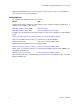
PCI CD/CDa Configurable DMA Interface User’s Guide Generating an Output Clock The formula for calculating the output frequency is: fout = (N * V * fxtal) / (m * R * H * L * X * 2) Figure 1.
Hardware Interface Protocol PCI CD/CDa Configurable DMA Interface User’s Guide Hardware Interface Protocol This section describes how to connect your device to a PCI CD/CDa interface, including the electrical characteristics of the signal, the signal descriptions, the timing specifications, and the connector pinout. Electrical Interface The PCI CD/CDa uses differential data transmission to transmit data at very high rates over long distances through noisy environments.
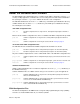
PCI CD/CDa Configurable DMA Interface User’s Guide Hardware Interface Protocol RS-422 The PCI CD-20 and PCI CDa RS-422 DMA interface protocols use RS-422 signal levels. RS-422 is defined by the Electronic Industries Association to provide robust high-speed data transmission. It allows signaling rates up to 10 MHz for short cables of up to 40 feet (12 meters) and cables of up to 4000 feet (1219 meters) at 100 KHz, as shown in Figure 3: Figure 3.
Hardware Interface Protocol PCI CD/CDa Configurable DMA Interface User’s Guide Signals The hardware flow control protocol assumes that FIFO or memory buffers on both ends implement almost-full and almost-empty thresholds. Therefore, when a BNR (board not ready) or DNR (device not ready) signal is sent to the transmitting device, the receiver can still accommodate enough data to allow for cable delay and synchronization. Table 1.
PCI CD/CDa Configurable DMA Interface User’s Guide Hardware Interface Protocol Timing The clock and data output timing is specified at the pins of the PCI CD/CDa connector. Table 2.
Hardware Interface Protocol PCI CD/CDa Configurable DMA Interface User’s Guide Figure 4.
PCI CD/CDa Configurable DMA Interface User’s Guide Hardware Interface Protocol Connector Pinouts The following pinout diagrams describe the connection from the PCI CD/CDa board to the cable. The board uses a high-density 80-pin I/O connector (EDT part number 012-10026), with a straight-shielded backshell (EDT part number 013-10287) or right-angle backshell (EDT 013-00458). NOTE Do not connect your own circuits to the unused pins, as they may be internally connected.
Registers PCI CD/CDa Configurable DMA Interface User’s Guide Registers The PCI CD/CDa has two memory spaces: the memory-mapped registers and the configuration space. Expansion ROM and I/O space are not implemented. Applications can access the PCI CD/CDa registers through the DMA library routines especially edt_reg_read() and edt_reg_write(), using the symbolic names listed under “Access” for each register.
PCI CD/CDa Configurable DMA Interface User’s Guide Registers Table 4.
Registers PCI CD/CDa Configurable DMA Interface User’s Guide Figure 6.
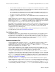
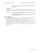
PCI CD/CDa Configurable DMA Interface User’s Guide Registers Figure 7. Scatter-gather DMA List Format Bits 63 Each address entry 32 31 control (unused) 16 D M A int 0 count All main DMA registers are read-only. Only the corresponding scatter-gather DMA registers must write to them. To initiate a DMA transfer, the driver performs the following general operations: 1. It sets up one or more scatter-gather DMA lists in host memory, using the format described above and illustrated in Figure 7. 2.
Registers PCI CD/CDa Configurable DMA Interface User’s Guide Main DMA Current Count and Control Register Size 32-bit I/O read-only Address 0x08 Access EDT_DMA_CUR_CNT Comment This register is automatically copied from the main DMA next count and control register after main DMA completes. Bit Description 31-16 Read-only versions of bits 31–16 of the Scatter-gather DMA current count and control register. 15–0 The number of words still to be transferred in the current DMA.
PCI CD/CDa Configurable DMA Interface User’s Guide Registers Scatter-gather DMA Next Address Register Size 32-bit I/O read-write Address 0x14 Access EDT_SG_NXT_ADDR Comment The driver software writes this register as described in step 2 of the list on page 21. Bit Description 31–0 The starting address of the next DMA.
Registers PCI CD/CDa Configurable DMA Interface User’s Guide Bit EDT_ Description 29 DMA_START Write a 1 to this bit to indicate that the values of this register and the SG DMA Next Address register are valid; this sets this bit to 0, indicating either that the copy is in progress, or that the device is waiting for the current DMA to complete. In either case, this register and the SG DMA Next Address register are not available for writing.
PCI CD/CDa Configurable DMA Interface User’s Guide Registers PLL Programming Register Size 8-bit I/O read-write Address 0x20 Access EDT_SS_PLL_CTL Comment PCI CDa only. The program set_ss_vco uses this register to program the serial interface of the four PLLs. Bit Name Description 7 PLL_SCLK Connected to all four PLL serial clock inputs. 6 PLL_DATA Connected to all four PLL serial data inputs. 5–4 not used 3–0 PLL_STROBE Connected to the strobe inputs of PLL 3–0, respectively.
Registers PCI CD/CDa Configurable DMA Interface User’s Guide Bit Description 8 A read-only bit indicating the position of the jumper that enables access to the protected area of the ROM that contains the executable program. A value of 1 indicates that the board can load a new program.
PCI CD/CDa Configurable DMA Interface User’s Guide Registers PCI Interrupt Status Register Size 32-bit I/O read-only Address 0xC8 Access EDT_DMA_STATUS Comment The driver uses this register initially to determine the source of a PCI interrupt. Bit PCD_ Description 16–31 not used 15 PCI_INTR PCI interrupt. When asserted, the PCI CD/CDa is asserting an interrupt on the PCI bus. 14 not used 13 RMT_INTR UI Xilinx interrupt. When asserted, the UI Xilinx interrupt is set.
Registers PCI CD/CDa Configurable DMA Interface User’s Guide Command Register Size 8-bit I/O read-write Address 0x00 Access PCD_CMD Bit PCD_ Description 4–7 STAT_INT_EN A value of one enables the corresponding STAT bit to cause an interrupt when it is asserted. 3 ENABLE Set to one to enable the PCI CD/CDa interface. This bit is set after the direction is chosen and typically after the first DMA buffer is ready. To reset direction or flags, toggle this bit.
PCI CD/CDa Configurable DMA Interface User’s Guide Registers Data Path Status Register Size 8-bit I/O read-only Address 0x01 Access PCD_DATA_PATH_STAT Bit PCD_ Description 7 IDV Reflects IDV state. (PCI CD only — spare on PCI CDa) 6 INFFAFULL If set, input FIFO is almost full. 4–5 INFFULL If set, input FIFO is full. 3 OVERFLOW This bit is asserted when the input FIFO is full and the IDV signal is high. Reset this bit with the ENABLE bit in the Command Register on page 28.
Registers PCI CD/CDa Configurable DMA Interface User’s Guide Stat Register Size 8-bit I/O read-only Address 0x03 Access PCD_STAT Bit PCD_ Description 7–4 STAT_INT Interrupt bits for the status bits. If the following conditions are both true, then the corresponding bit of these four can be asserted to cause a PCI Bus interrupt: • The device interrupt is enabled using the RMT_EN_INTR bit in the PCI Interrupt and UI Xilinx Configuration Register.
PCI CD/CDa Configurable DMA Interface User’s Guide Registers Direction Control Registers Size 8-bit I/O read-write Address 0x06, 0x07 Access PCD_DIRA, PCD_DIRB Comment PCI CD only — not used for PCI CDa The direction control registers determine whether the physical drivers or receivers on the PCI CD interface are inputs or outputs. The PCI CDa’s inputs are always enabled. To enable outputs, use bit 1 (SELRXT) of the Interface Configuration Register on page 33.
Registers PCI CD/CDa Configurable DMA Interface User’s Guide Programmed I/O Low Register Size 8-bit I/O read-write Address 0x08 Access PCD_PIO_OUTLOW Bit Description 7–0 Outputs data on the low eight bits of the 16-bit word. First write the low eight bits you wish to output to this register, then write the high eight bits to Programmed I/O High Register.
PCI CD/CDa Configurable DMA Interface User’s Guide Registers Interface Configuration Register Size 8-bit I/O read-write Address 0x0F Access PCD_CONFIG Bit PCD_ Description 7 SETIDV Set input data valid (used for debugging). 6 PIOEN Enables programmed I/O. A value of 1 translates DMA channel buffers and enables the Programmed I/O Low Register and the Programmed I/O High Register.
Registers PCI CD/CDa Configurable DMA Interface User’s Guide PCI CDa Registers The following four registers apply to the PCI CDa only. PLL Programming Register Size 8-bit I/O read-write Address 0x20 Access EDT_SS_PLL_CTL Comment The program set_ss_vco uses this register to program the serial interface of the PLL. Bit Name Description 7 PLL_SCLK Connected to the PLL serial clock input. 6 PLL_DATA Connected to the PLL serial data input.
PCI CD/CDa Configurable DMA Interface User’s Guide Registers LED Control Register Bit Size 8-bit I/O read-write Address 0x30 Access LED_CTL Name 7–3 Description not used 2 LED2 Set to turn on LED when both LED0 and LED1 are clear. 1–0 LED1, LED0 Set to specify the signal to drive the LED: LED1 0 0 1 1 EDT, Inc.
References PCI CD/CDa Configurable DMA Interface User’s Guide References ICS307 clock generator www.scantec.de/Hi-Q-News/2004/ICS-Versaclock/ics307.pdf PCI Local Bus SpecificationPCI Special Interest Group, www.pcisig.com RS-422 specification www.interfacebus.com/Design_Connector_RS422.htm Electrical Characteristics of Balanced Voltage Digital Interface Circuits LVDS specification EIA-644 (LVDS) Bus Standard EIA/TIA-644 Balanced (differential) interface [LVDS] LVDS Owner’s Manual www.national.