OPERATION AND INSTALLATION MANUAL WD/SDA/CDA SERIES 350 - 2100 CFM LARGE DEHUMIDIFYING DRYERS IMPORTANT: PLEASE READ CAREFULLY BEFORE ATTEMPTING TO INSTALL OR OPERATE EQUIPMENT Bulletin No: DH1-655 Part No: 882.00225.
Please note that our address and phone information has changed. Please reference this page for updated contact information. These manuals are obsolete and are provided only for their technical information, data and capacities. Portions of these manuals detailing procedures or precautions in the operation, inspection, maintenance and repair of the products may be inadequate, inaccurate, and/or incomplete and shouldn’t be relied upon.
Write Down Your Serial Numbers Here For Future Reference: _________________________ _________________________ _________________________ _________________________ _________________________ _________________________ We are committed to a continuing program of product improvement. Specifications, appearance, and dimensions described in this manual are subject to change without notice. DCN No. ____________ © Copyright 2005 All rights reserved.
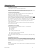
Shipping Info Unpacking and Inspection You should inspect your dryer for possible shipping damage. Thoroughly check the equipment for any damage that might have occurred in transit, such as broken or loose wiring and components, loose hardware and mounting screws, etc. In the Event of Shipping Damage According to the contract terms and conditions of the Carrier, the responsibility of the Shipper ends at the time and place of shipment. Notify the transportation company’s local agent if you discover damage.
Table of Contents CHAPTER 1: SAFETY................................................................ 6 1-1 1-2 1-3 1-4 1-5 How to Use This Manual ............................................................................................. 6 Safety Symbols Used in this Manual .....................................................................6 Safety Tag Information ................................................................................................ 7 Dryer Safety Tags .......................
5-5 5-6 5-7 5-8 5-9 5-10 5-11 5-12 5-13 Setting the High and Low Temperature Alarms ........................................................ 28 Temperature Controller Autotune Procedure ............................................................ 29 Temperature Controller Internal Switches................................................................. 29 Temperature Controller Anti-Tamper Lockout Switch ...............................................
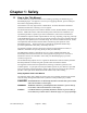
Chapter 1: Safety 1-1 How to Use This Manual Use this manual as a guide and reference for installing, operating, and maintaining your dehumidifying dryer. The purpose is to assist you in applying efficient, proven techniques that enhance equipment productivity. This manual covers only light corrective maintenance. No other maintenance should be undertaken without first contacting a service engineer. The Functional Description section outlines models covered, standard features, and safety features.
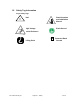
1-2 Safety Tag Information Dryer Safety Tags Hot! Read Operation and Installation Manual High Voltage Earth Ground Inside Enclosure PE Lifting Point 350-2100 cfm Dryers Chapter 1: Safety Protected Earth Ground 7 of 58
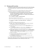
1-3 Warnings and Precautions Our equipment is designed to provide safe and reliable operation when installed and operated within design specifications, following national and local safety codes. This may include, but is not limited to OSHA, NEC, CSA, SPI, and any other local, national and international regulations.
1-4 Responsibility These machines are constructed for maximum operator safety when used under standard operating conditions and when recommended instructions are followed in the maintenance and operation of the machine. All personnel engaged in the use of the machine should become familiar with its operation as described in this manual. Proper operation of the machine promotes safety for the operator and all workers in its vicinity.
Learn and always use safe operation. Cooperate with co-workers to promote safe practices. Immediately report any potentially dangerous situation to your supervisor or appropriate person. REMEMBER: • NEVER place your hands or any part of your body in any dangerous location. • NEVER operate, service, or adjust the dryer without appropriate training and first reading and understanding this manual.
Before removing, adjusting, or replacing parts on a machine, remember to turn off all electric supplies and all accessory equipment at the machine, and disconnect and lockout electrical power. Attach warning tags to the disconnect switch. When you need to perform maintenance or repair work on a dryer above floor level, use a solid platform or a hydraulic elevator. If there is a permanently installed catwalk on your dryer, use it. The work platform should have secure footing and a place for tools and parts.
Chapter 2: Functional Description 2-1 Models Covered in This Manual This manual provides operation, installation, and maintenance instructions for WD/SDA/CDA 350, 425, 500, 600, 700, 850, 1000, 1250, 1500, 1800, and 2100 cfm large dehumidifying dryers in both standard 300˚ F and 400˚ F high temperature “-RT” models. Model numbers are listed on the serial tag. Make sure you know the model and serial number of your equipment before contacting the manufacturer for parts or service.
2-5 The Closed Loop Drying System ACS dryers force hot, dry air through the resin in the drying hopper, where the air picks up moisture from the material and is drawn back to the dryer. In the dryer, moisture is stripped from the air by a desiccant bed. The dried process air is then re-heated and delivered back into the drying hopper to dry material again. This system is a "closed loop", because ambient (outside) air is never introduced into the process air.
When a desiccant bed is online, it absorbs moisture from the process air. In time, the bed becomes saturated with moisture and needs to be regenerated. The dryer automatically redirects the process airflow to the second bed, and starts the regeneration cycle on the first bed.
Figure 3: ???????? 34" RADIUS DOOR CLEARANCE ELECTRICAL ENCLOSURE TOP VIEW DESICCANT TOWER (LEFT SIDE) OPTIONAL AFTERCOOLER A REGEN BLOWER AND FILTER PROCESS BLOWER PROCESS AIR OUTLET 1 2 3 1.5" MPT INLET 4 E B 1.5" MPT OUTLET C REAR VIEW PROCESS HEATER ? 1) PROCESS BLOWER PRES SWITCH 2) REGEN. DIRTY FILTER PRES. SWITCH 3) REGEN BLOWER PRES. SWITCH 4) DIRTY PROCESS FILTER PRES.
Figure 4: Dryer Dimensions WD Dryer Dimensions WD-2100 WD-1800 WD-1500 WD-1250 WD-1000 WD-850 100 100 100 84 84 84 A 90½ 90½ 90½ 88 88 88 B 82½ 82½ 82½ 56 56 56 C 44½ 44½ 44½ 34½ 34½ 34½ D 90.5 88 90.5 88 90.
Chapter 3: Installation 3-1 Work Rules The installation, operation, and maintenance of this equipment must be conducted in accordance with all applicable work and safety codes for the installation location. This may include, but not limited to, OSHA, NEC, CSA, and any other local, national and international regulations. 1. Read and follow these operating instructions when installing, operating and maintaining this equipment.
; Keep the delivery (to the drying hopper) hose as short as possible to minimize heat loss. Insulated hose is recommended and available for maximum energy savings. ; Do not use insulated hose on the return (from the drying hopper) ; Do not shorten the return hose. The return air to the blower must be 150°F or below. ; Make sure the hoses are not kinked.
Figure 5: Typical Control Panel WD Series Process Air Temperature Controller Dehumidifying Dryer Process Dirty Filter Process Delivery Temperature Process Blower On Process Heater On Process Dirty Filter High Process Air Temp Low Process Air Temp Process Blower Failure PV F Process Blower On Process Heater On SV Regeneration Dirty Filter Regeneration Heater On Regeneration Blower On Regen Blower On Regen Heater On Regeneration Exit Temperature Regen Dirty Filter DATA TEACH High Regen Air
Chapter 4: Control Panel 4-1 Control Panel Indicator Lights PROCESS BLOWER ON This indicator lights when the process blower is energized. PROCESS HEATER ON This indicator lights when the process air heaters are energized. HIGH PROCESS AIR TEMPERATURE ALARM ; This indicator lights when the temperature at the process air thermocouple is above the set high alarm value. ; When the indicator lights, the alarm relay is energized and all the heaters turn off while the blowers remain on.
; The alarm mode and value are factory-set to track 25°F below the process setpoint. The alarm value is a deviation above the process setpoint. ; This alarm is informational. If the alarm light stays lit for an extended period of time, check for blown fuses or possible burnt-out heaters. ; When the temperature at the thermocouple returns within limits, the alarm clears automatically. ; This alarm is delayed on initial start-up to avoid nuisance alarms. ; The alarm range may be altered. See Section 5-5.
VALVE POSITION ERROR A pair of position switches confirm proper shifting of the valves. If full travel is not confirmed by the switches, the cycle will not begin on the new bed. 4-2 Switches and Meters ON/OFF SELECTOR SWITCH This energizes or de-energizes the dryer's control power. START/STOP PUSH-BUTTON Press this momentary contact switch to start the dryer. Press this switch to shut down an operating dryer. The dryer shutdown sequence is: 1. Process heaters shut off immediately. 2.
; If one or two of a heater's three meters indicates a low reading, a burned-out heater is likely, and should be serviced. 4-3 PLC Control These dryers are equipped with an Omron C28K programmable logic controller (PLC). The "brick" type PLC has 28 I/O points - 16 inputs and 12 outputs. All inputs are 115 VAC, except for the 24 VDC input #1 from the dewpoint circuit board. All programming and logic is factory installed on an EPROM, and cannot be modified.
Figure 6: Process Air Temperature Controller 350-2100 cfm Dryers Chapter 4: Control Panel 24 of 58
4-5 Temperature Controller LED Indicators Process Value Numeric LED During normal operation, this red LED on the control displays the process temperature at the "To Process" thermocouple. It also lists parameters during setup and error messages if an error occurs. Set Value Numeric LED During normal operation, this green LED on the control displays the process set point you want the dryer to maintain. It also displays parameter and pre-set function values during setup.
4-6 Temperature Controller Keys – (See Figure 5 in Section 3-6) LEVEL KEY When pressed for two seconds or more, this key selects the next of the three indication levels (0, 1 and 2) where specific control parameters may be set. The control defaults to level 0 on power up. REMOTE KEY This key is on controls with optional communications. For information on RS-232C, RS-422, or RS-485 communications, refer to the Communications Manual [part number A0535959].
Chapter 5: Startup, Shutdown & Operation 5-1 Pre-Startup Checks ; Check the process and return hoses for tight connections. ; Check that all companion equipment, such as the drying hopper, loading system and aftercooler are ready for operation. ; Check the dryer electrical connections. Note: Clean the rust-preventive oil from inside the drying hopper. Failure to clean the hopper will cause fouling of the desiccant in the dryer, and will void the warranty.
6. If the dryer has an aftercooler, make sure there is proper flow of cooling water flow through the coil, and any trapped air has been bled from the system. 7. Make sure the damper on the hopper air inlet tube is about 50% open. 8. Remove the lower end of the 2½" flex hose from the tube stub on the lower drying hopper. Carefully adjust the damper valve on the return line back to the filter to achieve approximately 200 cfm air flow out of the flex hose. 9.
The low temperature alarm value is a deviation of the process air temperature set point. The alarm value will track the set temperature. If the low temperature alarm is set to "-25", a low temperature alarm occurs if the process air temperature falls more than 25°F below the process air temperature setpoint. 4. Press until the Level 0 values [process air temperature setpoint and process air temperature] are displayed. The High Temperature Alarm is now set.
5-9 Changing the Display from Fahrenheit to Centigrade To change the display from the factory °F setting to °C: 1. Disconnect main electrical power to the dryer. ON 1 2 3 4 5 6 2. Press up the latch at the bottom of the control module's front panel and slide out the control chassis. 3. Locate DIP switch SW201 {FUNCTION} on the right circuit board. 4. Slide the #5 pin to OFF. 5. Slide the chassis back into the control module's housing. 6.
5-11 Regeneration Monitoring System Signal Processor Dryer models 350 through 2100 have a 1/8 DIN signal processor that monitors the bleed air discharged from the desiccant tower being regenerated. The signal processor has four programmable temperature setpoints that, when reached, signal the PLC to cycle through the regeneration process. The PLC interprets the outputs from the signal processor depending on the part of the regeneration process currently underway.
• Press again to move one digit to the right. Then press desired value. to display the • Follow this procedure to set all four digits. to save the new value to the • When satisfied with the value displayed, press regeneration monitor's memory, and move on to the next parameter, if desired. • Press repeatedly to review the new settings.
Setting the Current Day of the Week, Hour and Minute: 1. Apply main power to the dryer. 2. Turn on the timer by sliding the left manual override switch to the "ON" position. The timer's memory is cleared on power up. MODE 3. Press and hold 4. Press or until TIM ADJ becomes visible and SUN blinks. until the current day of the week is displayed. to store the current day of the week in the timer's memory. The day of the week 5. Press indicator will stop blinking. 6.
7. Press blinking. once. The hour and minute display returns to zeroes and the hour indicator should be Setting the stop time: 1. Press or until the desired dryer shut down hour is displayed. The shut down time is set in a 24-hour format. 2. Press blinking. to store the shut down hour in the timer's memory. The hour indicator should stop 3. Press or until the desired dryer shut down minute is displayed. The minute indicator should be blinking. 4.
Chapter 6: Maintenance 6-1 Servicing the Process Air Filters (Models 350-700) WARNING: Operating the dryer without the process air filters installed will void the warranty. Filter Cleaning is an important part of dryer maintenance. Dryer models 350 through 700 have single high temperature [up to 350°F] cartridge cannister-type filter in the process air loop. It’s mounted above the process blower on the rear of the dryer.
to remove all dirt and suds (less than 40 psi, no nozzle). If the clean or downstream side of the filter has been contaminated with dirty water during the soak cycle, rinse from both sides. • Dry the filter before re-using. Circulate warm air at less than 160ºF. Do not use a light bulb to dry the filter. • Inspect for holes and tears by looking though the filter toward a bright light. Check for damaged gaskets or dented metal parts. Do not re-use a damaged filter.
service. Satisfactory filtration should be obtained through the second or third washing , however the dirt holding capacity of the filter decreases after each washing. After Each Cleaning: 6-4 • Inspect the filter element – hold a light bulb behind the element to find fatigued paper or residual dirt. • Inspect the end plates – damage here could allow air to bypass the filter. • Look for rust on the end plates and metal core – rust particles could flake off and contaminate the dryer and resin.
9. Remove the restriction from the filter element and re-install the clean filter. The alarm light should remain off. 6-6 Dewpoint Control System Service The Dewpoint Shift feature on dryer models 350 through 2100 depends on the proper operation of the dewpoint sensor and its control board. The dewpoint sensor is in the process airstream and is therefore susceptible to contamination. Dewpoint sensor life is dependent on: • Air temperature and flow passing over the sensor.
• Noticeable amounts of desiccant in the beds is a medium-brown color, or darker. If any of these signs are noticed, the desiccant in the desiccant beds should be replaced. Desiccant replacement kits are available from the Parts Department. If you wish, the desiccant beds can be repacked at your site by a technician. WARNING DESICCANT MATERIAL CAUSES EYE IRRITATION BREATHING MAY BE HARMFUL/MAY CAUSE SKIN IRRITATION ; Do not get in eyes. ; Avoid prolonged contact with skin.
Figure 6: Desiccant Amounts Required Dryer Model Large Bead 30 30 30 30 40 40 40 40 40 40 120 120 120 120 120 120 120 120 120 120 120 120 350 350-RT 425 425-RT 500 500-RT 600 600-RT 700 700-RT 850 850-RT 1000 1000-RT 1250 250-RT 1500 1500-RT 1800 1800-RT 2100 2100-RT 6-9 Desiccant Required per Tower Small Bead 76 76 90 90 100 100 120 120 35 35 120 120 130 130 180 180 240 240 310 310 360 360 Total 106 106 120 120 140 140 160 160 175 175 240 240 250 250 300 300 360 360 430 430 480 480 Process Heater Rep
6-10 Regeneration Heater Replacement Procedure Dryer models 350 through 2100 Dryers have four or eight three-phase regeneration heaters wired in the wye formation mounted in the insulated box directly above the lower valve. WARNING! WARNING! Disconnect and lock out power before heater replacement. 1. Access the regeneration heaters from the rear of the dryer. Remove the cover plate secured by two bolts. 3. Sketch the heater wiring configuration so the heaters may be re-assembled properly.
6-11 Restoring a Temperature Controller to the Factory Setup If the control's pre-set parameters have been tampered with and it will no longer control, try restoring the factory set up: 1. Turn off the power switch on the graphic display and remove all electrical power to the dryer. 2. Press up the latch at the bottom of the module's front panel and slide out the control chassis. 3. Locate the slide-type lockout switch [SW101 {PROTECT}] on the left circuit board. It should be Off.
Display Characters Sensor Type Switch Position Thermocouple Type R 0 Temp Range °C 0 - 1,700 Thermocouple Type S 1 0 - 1,700 0 - 3,000 Thermocouple Type K 2 Thermocouple Type J 3 Thermocouple Type T 4 Thermocouple Type E 5 -200 to 1,300 -100 to 900 -200 to 400 0 to 600 -300 to 2,300 -100 to 1,600 -300 to 700 0 to 1,100 Platinum RTD (JIS 1981) Platinum RTD (DIN) 6 -99.9 to 450.0 -99.9 to 450.0 -99.9 to 800.0 -99.9 to 800.0 Not Used Not Used 8 9 7 °F 0 - 3,000 9.
11. Slide the control chassis back into the control housing. The remaining parameters are set with the keypad. 12. Ready the dryer for startup with a real or simulated load. Restore the electrical power. 13. Turn the control power on. The PV LED will display four zeros [0000] and then display the current process air temperature. 14. Press to page through the Level-0 control parameters.
Figure 7: Factory Pre-Set Control Parameters Parameter Parameter Description Setting Levels 0 1 PV LED Display Dryer SV LED Setting Display at Power Up 10°F Alarm Range 10°F Proportional Bandwidth Reset Time 90.0 Seconds 20 Seconds Rate Time 0°F Lower Limit Value of Control Range Dead Band 250°F Cooling Coefficient 1.
Figure 8: Process Temperature Control Error Messages Message [FLASHES] Cause Input temperature has risen beyond the upper limit of the temperature range by more than 20°C [68°F] c Input temperature has fallen below the lower limit of the temperature range by more than 20°C [68°F] d The thermocouple has burned out or the short circuit bar has been removed. The platinum RTD has burned out or A and B have been short circuited. Memory failure (E111) or analog to digital converter failure (E333) has occurred.
Figure 9: Regeneration Monitor Signal Processor Error Messages Output Status Item Device Failure Condition Error Message CPU RAM error, external memory error, memory data error. OFF Corrupted Data Sensor Error Overflow, Underflow Output Type Change Breakage or short circuit of sensor. When the thermocouple is used, terminals 11 and 13 are not short circuited. Input value or display value outside range. When output type has changed. Output Type Error Output type other than specified.
6-12 Regeneration Monitor Advanced Programming The regeneration monitor has three menu levels, numbered 0 through 2. Each menu level allows specific parameters to be viewed and/or set. Moving Between Levels Level 0, the RUN mode, is the default and automatically appears when the dryer is powered up. To move to Level 1, press and hold for 2 seconds. When Level 1 is reached, press and hold both and for 1 second to move up a level, or move back to RUN mode by pressing See the flow chart below. Press 2 sec.
LEVEL 1 In this level, the four setpoints can be changed, plus Hysteresis, Input Shift and Security Protection can be set. Setpoints Use to move from one parameter to the next. Hysteresis When the desired parameter appears to on the LED display, press select that parameter for programming. The parameter’s current value appears on the LED display. Input Shift When the desired parameter is Security Protection displayed, use and to view and/or change the parameter.
Press after appears on the LED display. Use and to set the value. Then press to save the new setting to memory. Security Protection When Security Protection is enabled, the setpoints can’t be changed when the Regeneration Monitor is in “RUN” mode. The setpoints can only be changed in Level 1 using the function. Press after appears on the LED display.Use to toggle between ON and OFF. The factory setting is “OFF”. When the selection has been made, press memory.
LEVEL 2 In this level, parameters such as the type of temperature sensor connected to the regeneration monitor, Fahrenheit/centigrade display, and display refresh cycle can be set. moves from one parameter to the next. When the desired parameter appears on the LED display, press to select that parameter for programming. The current value of the parameter is then displayed on the LED display. Use and Sensor Input Type Scale Indication °C or °F Display Refresh Cycle to change the setting.
Chapter 7: Troubleshooting PROBLEM Little or no air coming from process delivery tube. POSSIBLE CAUSE A. Dirty Filters B. Desiccant beds contaminated by material or plasticizer leaking into the system. See Sec. 6-6. C. Blower fuse(s) blown. D. Overload tripped. CORRECTIVE ACTION A. Clean or replace filters. B. Replace desiccant C. Fix problem and Replace fuse(s). D. E. Blower fins filled with dust or contaminants. Suction in delivery tube, pressure from the return tube. A.
PROBLEM Loss or reduction of process air temperature. POSSIBLE CAUSE A. Process heaters are faulty. B. Solid-state temperature controller faulty. C. Process temperature was adjusted in error by plant personnel. Loss or reduction in drying capacity. A. Process heaters are faulty. B. Desiccant beds are contaminated. C. Material being dried differs from material specified at the time of purchase. D. Break in flex hose to/from drying hopper. E. Airflow valves sticking or failing to shift. F.
PROBLEM Material in drying hopper cakes, or meltdown occurs. POSSIBLE CAUSE A. Process temperature set too high due to operator error. B. High temperature alarm not set properly. C. Process set point is out of acceptable range. Poor Dew Point Performance. 350-2100 cfm Dryers A. Burned out regeneration heater. B. Contaminated or worn out desiccant. C. Leaking process air hoses. D. Dryer is being operated beyond its capacity. E. Bad dew point sensor. F. Fouled dew point sensor manifold.
Chapter 8: Appendix 8-1 Customer Satisfaction Warranty Program The terms and conditions of the warranty set forth are for one (1) year from the original date of purchase by the original purchaser. The manufacturer warrants to the original purchaser the product and/or goods to which this disclaimer is attached, and manufactured by us, to be free from defects in material and workmanship under normal use and service.
-Notes- 350-2100 cfm Dryers Chapter 8: Appendix 56 of 58
Preventive Maintenance Checklist Dehumidifying Dryers Dryer Model # EVERY WEEK Serial # Date/ By Date/ By Date/ By Date/ By Date/ By Date/ By Date/ By Date/ By Date/ By Date/ By Date/ By Date/ By Date/ By Inspect all filters for wear, replace/clean if dirty or worn Check air regulator to make sure pressure is 6080 psi.
8-2 Technical Assistance Parts Department Call toll-free 7am–5pm CST [800] 423-3183 or call [630] 595-1060, Fax [630] 475-7005 The ACS Customer Service Group will provide your company with genuine OEM quality parts manufactured to engineering design specifications, which will maximize your equipment’s performance and efficiency. To assist in expediting your phone or fax order, please have the model and serial number of your unit when you contact us.