DC730.. - Built Under Double Ovens Manual for Installation, Use and Maintenance Customer Care Department • The Group Ltd. • Harby Road • Langar • Nottinghamshire • NG13 9HY T : 01949 862 012 F : 01949 862 003 E : service@cda.eu W : www.cda.
Important This appliance is designed and manufactured solely for the cooking of domestic (household) food and is not suitable for any non domestic application and therefore should not be used in a commercial environment. The appliance guarantee will be void if the appliance is used within a non domestic environment i.e. a semi commercial, commercial or communal environment. The CDA Group Ltd cannot be held responsible for injuries or losses caused by incorrect use or installation of this product.
Before Using for the First Time – Read the instructions carefully before installing and using the appliance. – After unpacking the appliance, check that it is not damaged. In case of doubt, do not use the appliance and contact your supplier or a qualified engineer. – Remove all the packing materials (i.e. plastic bags, polystyrene foam, etc.) and do not leave it around within easy reach of children, as these may cause serious injuries. The packaging materials are recyclable.
Important Safeguards and Recommendations – Do not carry out any cleaning or maintenance without first disconnecting the appliance from the electrical supply. – During and after use of the double oven, certain parts will become very hot. Do not touch hot parts. – After use always ensure that the control knobs are in the OFF position ( - ). – Household appliances are not intended to be played with by children. – Keep children away from the oven during use.
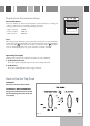
Control Panel 7 6 A 1 2 5 3 4 Fig. 1 Controls Description 1. Oven temperature knob (Top oven) 2. Function selector knob (Top oven) 3. Function selector knob (Lower main oven) 4. Oven temperature knob (Lower main oven) 5. Digital electronic programmer (Lower main oven only) Warning Lights: 6. Main oven temperature indicator light 7.
Top Natural Convection Oven General Features This oven features 2 different thermostatic control functions to satisfy all cooking requirements, provided by 3 heating elements: – Upper element, 700 W – Lower element, 1000 W – Grill element, 2000 W Note: When using for the first time, you are advised to operate the oven at maximum temperature (thermostat knob on the maximum position) for approximately one hour in the mode and for another 15 minutes in the mode in order to eliminate any traces of grea
Thermostat Knob (Fig. 2) This only sets the cooking temperature and does not switch the oven on. Rotate clockwise until the required temperature is reached (from 50 °C to 250 °C). The thermostat indicator light will illuminate when the oven is switched on and turns off when the oven reaches the correct temperature. The light will cycle on and off during cooking in line with the oven temperature. Function Selector Knob (Fig.
Oven Cooking Before introducing the food, preheat the oven to the desired temperature. For a correct preheating operation, it is advisable to remove the tray from the oven and introduce it together with the food, when the oven has reached the desired temperature. Check the cooking time and turn off the oven 5 minutes before the theoretical time to recuperate the stored heat. Use of the Grill – Preheat the oven for about 5 minutes with the door closed.
Lower Main Fan Oven General Features The heating and cooking in electrical hot air ovens take place by forced convection. The element which make this process take place is: – Circular element 1900 W Note: Upon first use, it is advisable to operate the oven at the maximum temperature (thermostat knob on the maximum position) for 60 minutes in the position to eliminate possible traces of grease on the heating element.
How to Use the Lower Oven WARNING: The door is hot, use the handle. ATTENTION - MOST IMPORTANT Pay special attention not to touch the hot heating element inside the oven cavity. Thermostat Knob (Fig. 5) This only sets the cooking temperature and does not switch the oven on. Fig. 4 Fig. 5 Rotate clockwise until the required temperature is reached (from 50 °C to 250 °C).
Lower Oven Cooking Advice Cooking with Forced Air Fan cooking is more economical and quicker than cooking in a conventional oven. The moving hot air surrounds the food and penetrates it more quickly than in a conventional oven. The oven can be filled with different dishes all requiring the same cooking temperature. Subtract 10 minutes per hour for every dish requiring a cooking time of more than 1 hour and reduce the heat by 1020°C; the hotter the oven, the more the temperature can be reduced.
Electronic Programmer (Lower Main Oven only) The electronic programmer is a device that groups together the following functions: – 24 hour clock with illuminated display – Timer (up to 23 hours and 59 minutes) – Programme for automatic oven cooking – Programme for semi-automatic oven cooking. Description of the Buttons: Symbols Description Timer Cooking time Description of the Illuminated Symbols: Symbols A flashing A always lit Description Programmer in automatic position but not programmed.
Setting Time of Day (fig. 7) The programmer is provided with an electronic clock with luminous figures showing the hour and minutes. The first time the oven is connected up to the electricity supply and after a power cut, three zeroes will flash on the programmer display. To adjust the time, the two buttons must be pressed simultaneously and then the button or until the correct time is set. Setting speed automatically increases if you keep the setting buttons pressed.
Minute Minder The minute counter function consists simply of an acoustic signal which can be set for a maximum of 23 hours 59 minutes. If the letter A is flashing, press the two buttons To set the time, press button (Fig. 9). The symbol and then button simultaneously. or until the required time appears on the display will come on. Countdown will begin immediately and can be seen on the display at any time by simply pressing button .
Semi - Automatic Cooking This automatically switches the oven off after the required cooking time. There are two methods of semiautomatic cooking: 1. METHOD: Programming the cooking time (Fig. 11) – Set the cooking time by pressing button and then button if you have gone beyond the required time. The letter A and the symbol will appear. to move forward or 2. METHOD: Programming the end of cooking time (Fig.
Automatic Cooking To cook in the oven in automatic mode follow the instructions below: 1. Set the cooking time 2. Set the end of cooking time 3. Set the cooking temperature and function These operations are carried out as follows: 1. Set the cooking time by pressing button and then have gone beyond the required time (fig. 13). The letter A and the symbol appear. to move forward or to move back if you 2. Press button ; the cooking time already added to the clock time appear.
Do’s and do not’s – Do always grill with the oven door closed. – Do read the user instructions carefully before using the double oven for the first time. – Do allow the double oven to heat for one and a half hours, before using for the first time, in order to expel any smell from the new oven insulation, without the introduction of food. – Do clean your double oven regularly. – Do remove spills as soon as they occur. – Do always use oven gloves when removing food shelves and trays from the ovens.
Care and Maintenance It is advisable to clean when the appliance is cold and especially for cleaning the enamelled parts. Avoid leaving alkaline or acidic substances (lemon juice, vinegar, etc.) on the surfaces. Avoid using cleaning products with a chlorine or acidic base. WARNING When correctly installed, your product meets all safety requirements laid down for this type of product category.
Replacing the Oven Lights WARNING: Ensure the appliance is switched off before replacing the lamp to avoid the possibility of electric shock. – Let the oven cavity and the heating elements to cool down; – Switch off the electrical supply; – Unscrew the protective cover C (fig. 15); – Unscrew and replace the bulb B with a new one suitable for high temperatures (300°C) having the following specifications: 230V, E14 and same power (check watt power as stamped in the bulb itself) of the replaced bulb.
Assembling and Dismantling of the Side Runner Frames – Assemble the wire racks to the oven walls using the 2 screws (Figs. 16-18). – Slide the tray and rack into the runners (Figs. 17-19). The rack must be fitted so that the safety catch, which stops it sliding out, faces the inside of the oven. – To dismantle, operate in reverse order. Fig. 16 Fig. 17 Fig. 18 Fig.
Oven Doors Removing the Oven Doors The oven doors can easily be removed as follows: – Open the door to the full extent (fig. 20a). – Open the lever A completely on the left and right hinges (fig. 20b). – Hold the door as shown in fig. 20. – Gently close the door (fig. 20c) until left and right hinge levers A are hooked to part B of the door (fig. 20b). – Withdraw the hinge hooks from their location following arrow C (fig. 20d). – Rest the door on a soft surface. Fig.
Oven Doors - Removable Inner Pane of Glass Cleaning the Panes of Glass The oven doors are fitted with no. 2 panes: - no. 1 outside; - no. 1 inner; To clean the panes on both sides it is necessary to remove the inner pane as follows. Do not use harsh abrasive cleaners or sharp metal scrapers to clean the oven door glass since they scratch the surface, which may result in shattering of the glass. Removing the Inner Pane of Glass Fig. 21 The oven door has two panes.
Replacing the Inner Pane of Glass 1. Make sure the door is locked open (see fig. 23). 2. Replace the inner pane: – Check that the four rubber pads are in place (D in Fig. 26). – Insert the pane in the left E and right F slide guides (fig. 27), and gently slide it to the retainers H (fig. 28). – Top oven door only: reassemble the seal G in the correct way (fig. 29) by hooking the no. 3 fixing hooks in the proper holes (fig. 30).
ADVICE FOR THE INSTALLER Important Appliance installation and maintenance must only be carried out by QUALIFIED TECHNICIANS and in compliance with the local safety standards. • Failure to observe this rule will invalidate the warranty. • Always disconnect the appliance from the electrical supply before carrying out any maintenance operations or repairs. • The walls surrounding the oven must be made of heat-resistant material. • Taking care NOT to lift the oven by the door handle.
To Build in the Double Oven • The appliance should be installed by a QUALIFIED INSTALLATION TECHNICIAN. The appliance must be installed in compliance with regulations in force. The built under double oven shall be fitted under the working surface into a kitchen base unit (width and depth 60 cm) but you must ensure that it is properly ventilated. Installation requires a compartment as illustrated and described in next chapters: • Installation "A" between Existing Side Cabinets (560 or 600 mm GAP) (figs.
Installation "A" between Existing Side Cabinets (560 or 600 mm GAP) (figs. 32, 33, 34, 36) – Mount the 2 (two) metal supports “B” (supplied with the appliance in a separate kit) as indicated in Figs. 33 or 36). – Fig. 36 only - prepare 2 wood uprights “A” (width 20-50 mm, thickness 18 mm, length 650 mm); mount the 2 wood uprights “A” to the cabinet walls as indicated in figure. – Build in the double oven making it slide on the metal supports “B”.
Installation “B” Installation “A” 600 mm Gap Fig. 34 Pre existing 600 mm cabinetry Fig. 35 600 mm Gap 570 (*) M easure calculated from the underneath of the worktop to the top support base of the “B” supports. min WARNING ! VERY IMPORTANT The underside of the cabinet shall be opened to allow correct air circulation. 720 min (*) 650 A 538 718 B 600 18 A 4 54 20 22 20 Fig.
Installation "C" By Using Housing Unit (figs. 37, 38, 39) • Remove the single oven shelf, if fitted, as indicated in figure 37. • Remove the upper cross member support as indicated in figure 38. • Cut the bottom of the housing as indicated in figure 38. • Screw oven base housing to adjoining cabinetry by suitable screws (not supplied) as indicated in figure 39. • Check the position of the cabinet legs to ensure the cut-out does not interfere with the legs support.
Installation “C” 720 min Measure calculated from the underneath of the worktop to the top support base of the “B” supports. 600 30 B 40 40 Cabinet for installing the oven Support base 42 Remove single oven shelf, if fitted. B Fig. 37 30 15 15 25 36 18 Fig. 38 18 30 538 718 B 4 54 595 Fig. 39 Fig. 8.
Fixing the Double Oven The double oven should then be secured by 6 screws (not supplied) fitted into the holes provided at the sides of the oven (Fig. 40). If you open the oven doors, you will see some screw holes. Remember the housing should not be free standing but be secured to the wall and/or adjacent fittings. Note: It is essential that when installing your double oven, adequate air circulation is available within the installation.
IMPORTANT: – To avoid damage to the lower trim please note the following instructions. – The lower trim is designed to allow for good air circulation and the correct opening of the oven door. – To ensure the trim is not damaged due to the appliance being placed on the floor, the appliance should be suitably supported as in below illustrations. – After installation the appliance door should be slowly opened to ensure no damage has occurred.
Electrical Installation For your safety please read the following information: WARNING! Before effecting any intervention on the electrical parts the appliance must be disconnected from the network. IMPORTANT: The oven must be installed in accordance with the manufacturer’s instructions. Incorrect installation, for which the manufacturer accepts no responsibility, may cause damage to persons, animals and things.
Connection the Double Oven Mains Cable Important! This oven must be connected to the mains power supply only by a suitably qualified person. Unscrew the screws A securing the cover plate B behind the oven (fig. 44). – Remove the cover plate B. – Remove the screws C from the cable clamp (fig. 45). – Insert the mains cable (type H05RR-F or H05VV-F - 3x2,5 mm2 section) into the cable protector P. – Connect the phase and earth cables to the mains terminal connection block D.
Appliance Servicing CDA provide a quality and effective after-sales service to cover all your servicing needs. Please attach your receipt to this page for safekeeping. Please help us to help you by having the following information available when booking a service-call: 1. Model type, make and model – see the product data plate. 2. Evidence of installation / purchase date 3. Retailer where appliance was purchased 4. Clear and concise details of the fault 5.
Guarantee CDA appliances carry a five-year parts and a one-year labour guarantee. CDA will repair or replace any defect or part attributable to faulty material or workmanship. Within the first year this will be free of both labour and parts charges. After the first year and within five years, the parts will be supplied free of charge provided that the repair is carried out by an agent authorised by CDA and the labour will be charged at the commercial rate applicable at the time of repair.
Cod. 1103550- ß2 To contact our Customer Care Department, or for Service, please contact us on the details below. Customer Care Department • The Group Ltd. • Harby Road • Langar • Nottinghamshire • NG13 9HY T : 01949 862 012 F : 01949 862 003 E : service@cda.eu W : www.cda.