BUILT UNDER DOUBLE OVEN Instruction for the use - Installation advice KEEP IN A SAFE PLACE Before operating this oven, please read these instructions carefully
Dear Customer, Thank you for having purchased and given your preference to our product. The safety precautions and recommendations within this booklet are for your own safety and that of others. They will also provide a means by which to make full use of the features offered by your appliance. Please preserve this booklet carefully. It may be useful in future, either to yourself or to others in the event that doubts should arise relating to its operation.
DECLARATION OF CE CONFORMITY • This double oven has been designed to be used only for cooking. Any other use (such as heating a room) is improper and dangerous. • This double oven has been designed, constructed, and marketed in compliance with: - safety requirements of EU Directive “Low voltage” 2006/95/EC - safety requirements of EU Directive “EMC” 89/336/EEC; - requirements of EU Directive 93/68/EEC. IMPORTANT INFORMATION FOR CORRECT DISPOSAL OF THE PRODUCT IN ACCORDANCE WITH EC DIRECTIVE 2002/96/EC.
BEFORE USING FOR THE FIRST TIME ■ ■ ■ ■ ■ Read the instructions carefully before installing and using the appliance. After unpacking the appliance, check that it is not damaged. In case of doubt, do not use the appliance and contact your supplier or a qualified engineer. Remove all the packing materials (i.e. plastic bags, polystyrene foam, etc.) and do not leave it around within easy reach of children, as these may cause serious injuries. The packaging materials are recyclable.
IMPORTANT SAFEGUARDS & RECOMMENDATIONS ■ ■ ■ ■ ■ ■ ■ ■ ■ ■ ■ ■ ■ ■ ■ ■ ■ Do not carry out any cleaning or maintenance without first disconnecting the appliance from the electrical supply. During and after use of the double oven, certain parts will become very hot. Do not touch hot parts. After use always ensure that the controls are in the “0” OFF position. Household appliances are not intended to be played with by children. Keep children away from the double oven during use.
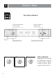
C O N T R O L PA N E L 1 TOP OVEN CONTROLS Top oven temperature indicator lamp Top oven power on indicator lamp FUNCTION TEMPERATURE 0 50 75 100 125 250 225 150 200 TOP OVEN 175 TOP OVEN A Fig. 1.1 Cooking functions knob Temperature knob A1 A2 TYPES OF THERMOSTAT A3 50 50 50 100 100 MAX 250 100 250 225 200 6 150 200 150 150 200 Depending on the models the thermostat could be of type A1 (50 to 225°C) or type A2 (50 to 250°C) or type A3 (50 to MAX).
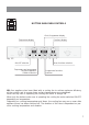
BOTTOM MAIN OVEN CONTROLS Clock / Programmer display Temperature display Functions display TEMPERATURE 50 75 100 125 150 TOP OVEN TOP OVEN Fig. 1.2 ON/OFF selection Temperature and programmer functions regulation, Childlock selection Oven functions selection Programmer functions selection NB: Your appliance has been fitted with a cooling fan to achieve optimum efficiency of the controls and to ensure lower surface temperatures are maintained.
TOP OVEN 2 N ATURAL C ONVENTION E LECTRIC O VEN GENERAL FEATURES This oven features 2 different thermostatic control functions to satisfy all cooking requirements, provided by 3 heating elements: • Upper element, • Lower element, • Grill element, 700 W 1000 W 2000 W NOTE: When using for the first time, you are advised to operate the oven at maximum temperature (thermostat knob on the maximum position) for approximately one hour in the mode and for another 15 minutes in the mode in order to eliminate any
THERMOSTAT KNOB (fig. 2.1) To turn on the heating elements of the oven, set function selector knob to the required position and the thermostat knob to the desired temperature. To set the temperature, turn the thermostat control knob indicator mark to the required temperature. The elements will turn on or off automatically which is determined by the thermostat. The operation of the heating elements is signalled by a light placed on the control panel. FUNCTION SELECTOR KNOB (fig. 2.
COOKING ADVICE OVEN COOKING Before introducing the food, preheat the oven to the desired temperature. For a correct preheating operation, it is advisable to remove the tray from the oven and introduce it together with the food, when the oven has reached the desired temperature. Check the cooking time and turn off the oven 5 minutes before the theoretical time to recuperate the stored heat. USE OF THE GRILL Leave to warm up for approximately 5 minutes with the door closed.
BOTTOM MAIN OVEN 3 F ULL E LECTRONIC M ULTIFUNCTION O VEN GENERAL FEATURES This multifunction electronic oven has 4 heating elements which allow you to choose between 9 cooking programmes: IMPORTANT Do not touch the hot heating elements inside the oven cavity. • • • • Attention: the oven door becomes very hot during operation. Use the handle. Keep children away.
OPERATING PRINCIPLES Heating and cooking in the FULL ELECTRONIC MULTIFUNCTION oven are obtained in the following ways: a. by normal convection The heat is produced by the upper and lower heating elements. b. by semi-forced convection from the bottom The heat produced by the lower heating element is distributed throughout the oven by the fan. c. by radiation The heat is radiated by the infrared grill element. d. by double radiation The heat is radiated by the infrared grill and the top heating elements. e.
U SING THE M AIN O VEN E LECTRONIC D ISPLAY DIGITS - Oven switched on: Time of day and selected function (alternating) - Oven switched off: Time of day SYMBOL Lit = minute minder in operation Flashing = countdown completed by the minute minder SYMBOL SYMBOL Lit = semi-automatic or automatic cooking programmed Flashing = semi-automatic or automatic cooking completed Lit = operation of heating elements (cooking functions) Flashing = semi-automatic or automatic cooking completed FIG. 3.
ELECTRONIC CONTROLLER FEATURES It • • • • • • • • performs the following functions: 24 hours clock with illuminated display. Timer (minute minder: up to 600 minutes - 10 hours). Programme for semi-automatic oven cooking (up to 600 minutes - 10 hours - of cooking time). Programme for automatic oven cooking (up to 600 minutes - 10 hours - of cooking time). Automatic switch off. “Childlock” safety (deactivation of the controller selections). Oven functions and temperature selection.
TURNING THE OVEN ON AND OFF To turn the oven ON: • Touch the key “ ” and hold until “On” appears on the clock/programmer display. • You can now operate your oven. The time of the day appears on the clock/programmer display (followed by the programme number “Pr01, Pr02, ...”). To turn the oven OFF: • Touch the key “ ” and hold until “OFF” appears on the clock/programmer display. • The oven is turned off (“stand-by” condition) and the time of the day appears on the clock/programmer display.
CHILDLOCK SAFETY To activate the Childlock option touch the “ ” and “ ” keys simultaneously and hold until the clock/programmer display shows “n--0” and then “On”. Then the time of the day appears again (followed by the selected programme number “Pr01, Pr02, ...” when the oven is ON). The temperature display shows “ ”. When the Childlock option has been selected it is only possible to turn off the oven (stand-by mode) and operate the timer (minute minder).
USING THE TIMER (MINUTE MINDER) You can use the timer at any time, even when the oven is not in use or switched off (stand-by mode). The timer does not turn the oven off. Remember to turn off the oven manually. The timer can be set for up to 600 minutes (10 hours). To set the timer: • Select “bELL” on the clock/programmer display by using the key “ ” and then, with “---’” flashing on the central display, touch “ ” and “ ” keys and set the time in minutes. • To reset the time touch the “ ” or “ ” key.
U SING S ELECTING M AIN O VEN C OOKING F UNCTIONS THE THE Clock/ Programmer display Functions display setting Oven cooking function When selection a cooking function the relative programme number and the symbol are activated. setting Fig. 3.
U SING THE M AIN O VEN SELECTING THE TEMPERATURE Cooking temperature All cooking functions start to operate with a pre-set temperature which can be modified, at any time, by touching the relative “+” and “–” keys positioned below the temperature display. “Celsius degrees” symbol The symbol is lit when the temperature is displayed. Childlock symbol When the symbol is permanently lit the Childlock option is activated. Fig. 3.
USING THE OVEN - COOKING FUNCTIONS Turn on the oven as indicated in the “TURNING THE OVEN ON AND OFF” chapter. Select the oven function and temperature as indicated in the previous pages. IMPORTANT: the cooking function and temperature can be modified at any time during the normal, semi-automatic or automatic cooking. Please remember to set the Childlock option in the presence of children. OVEN LAMP When the oven is turned ON the oven light comes on and the relative symbol is lit in the functions display.
FAN LOWER HEAT The lower heating element and the fan motor are switched on. The heat coming from the bottom is diffused by forced convection and the temperature must be set between 50 and 250°C. The pre-heating temperature is set at 190°C. To change the temperature, follow the instructions in the “SELECTING THE TEMPERATURE” chapter. Recommended for: This mode is particularly suitable to complete cooking of dishes that require higher temperature at the bottom.
VENTILATED GRILL COOKING The infrared heating element and the fan are switched on. The heat is mainly diffused by radiation and distributed by the fan throughout the oven. Use with the oven door closed and the temperature between 50 and 200°C maximum. The pre-heating temperature is set at 200°C. To change the temperature, follow the instructions in the “SELECTING THE TEMPERATURE” chapter. Recommended for: For fast browning and sautéing , i. e. veal steak, steak, hamburger, etc.
CONVECTION COOKING WITH FAN The upper and lower heating elements and the fan are switched on. The heat from the top and the bottom is diffused by fan convection. The temperature can be set between 50 and 250°C. The pre-heating temperature is set at 175°C. To change the temperature, follow the instructions in the “SELECTING THE TEMPERATURE” chapter. Recommended for: For foods of large volume and quantity which require the same internal and external degree of cooking; e.g.
SPECIAL “BOOSTER” PROGRAMME This special programme allow a fast pre-heating of the cavity by a combination of the heating elements. VERY IMPORTANT NOTE: This special programme must be operated without food inside the oven cavity. Introduce the food to be cooked only at the end of the BOOSTER programme. It is not possible to activate this option: • If a semi-automatic or automatic cooking has been programmed. • For the OVEN LAMP, GRILLING, TURBO GRILL and VENTILATED GRILL COOKING functions.
USING THE OVEN MANUALLY Turn the oven ON as indicated in the “TURNING THE OVEN ON AND OFF” chapter. Operate the oven manually by selecting the oven function and temperature as indicated in the “SELECTING THE COOKING FUNCTIONS” and “SELECTING THE TEMPERATURE” chapters. The oven will start to operate about four seconds after your last selection.
USING THE OVEN AUTOMATICALLY Use automatic cooking to automatically turn the oven on, cook, and then turn the oven off. 1. Check the clock shows the correct time. 2. Select the function and temperature. The oven will come on. 3. Decide how long the food will take to cook, allowing time for pre-heating if necessary. 4.
COOKING ADVICE STERILISATION Sterilisation of foods to be conserved, in full and hermetically sealed jars, is done in the following way: a. b. c. d. Set the function . Set the temperature at 185 °C and preheat the oven. Fill the grill pan with hot water. Set the jars into the grill pan making sure they do not touch each other and the door and set the temperature at 135 °C. When sterilization has begun, that is, when the contents of the jars start to bubble, turn off the oven and let cool.
USE OF THE GRILL AND TURBO GRILL Choose or function and set the temperature between 50 and 225°C maximum. Preheat for approximately 5 minutes with the door closed. Put the grill pan as close to the grill as possible. Always grill with the oven door closed. Do not grill for longer than 30 minutes at any one time. Attention: the oven door becomes very hot during operation. Keep children away.
4 CLEANING AND MAINTENANCE GENERAL ADVICE Important: Before any operation of cleaning and maintenance disconnect the appliance from the electrical supply. It is advisable to clean when the appliance is cold and especially for cleaning the enamelled parts. Avoid leaving alkaline or acidic substances (lemon juice, vinegar, etc.) on the surfaces. Avoid using cleaning products with a chlorine or acidic base.
ENAMELLED PARTS All the enamelled parts must be cleaned with a sponge and soapy water only or other non-abrasive products. Dry preferably with a microfibre or soft cloth. STAINLESS STEEL SURFACES (MODELS WITHOUT ANTI-FINGERPRINT TREATMENT), ALUMINIUM PARTS AND PAINTED OR SILK-SCREEN PRINTED SURFACES Clean using an appropriate product. Always dry thoroughly. IMPORTANT: these parts must be cleaned very carefully to avoid scratching and abrasion. You are advised to use a soft cloth and neutral soap.
OVEN FITTING OUT MODELS WITH EMBOSSED CAVITY The oven shelves are provided with a security block to prevent accidental extraction. They must be inserted operating as per figure 4.1a - 4.1b. To pull them out operate in the inverse order. TOP OVEN BOTTOM MAIN OVEN Fig. 4.1a Fig. 4.
MODELS WITH WIRE RACKS – Assemble the wire racks to the oven walls using the 2 screws (Fig. 4.2a - 4.2b). In the models with catalytic panels interpose the catalytic panels “A” with the arrow up (fig. 4.2a - 4.2b). – Slide in, on the guides, the shelf and the tray (fig. 4.3a - 4.3b). The shelf must be fitted so that the safety catch, which stops it sliding out, faces the inside of the oven. – To dismantle, operate in reverse order. TOP OVEN BOTTOM MAIN OVEN A A 32 Fig. 4.2a Fig. 4.2b Fig. 4.3a Fig.
TELESCOPIC SLIDING SHELF SUPPORTS (SUPPLIED WITH SOME MODELS ONLY) The telescopic sliding shelf supports make it safer and easier to insert and remove the oven shelves and trays. They stop when they are pulled out to the maximum position. Important! When fitting the sliding shelf supports, make sure that you fit: – The slides to the top wire of a rack. They do not fit on the lower wire. – The slides so that they run out towards the oven door. – Both sides of each pair of shelf slides.
To remove the telescopic sliding shelf supports: – Remove the side racks by unscrewing the fixing screws (Figs. 4.6 - 4.7). – Lay down the telescopic sliding shelf support and side racks, with the telescopic sliding shelf support underneath. – Find the safety locks. These are the tabs that clip over the wire of the side rack (arrow 1 in Fig. 4.8). – Pull the safety locks away from the wire to release the wire (arrow 2 in Fig. 4.8). Fig. 4.6 Fig. 4.7 1 2 1 34 Fig. 4.
MODELS WITH SLIDING SHELVES – Assemble the sliding shelves on the oven wall as in Fig. 4.9a - 4.9b. In the models with catalytic panels interpose the catalytic panels “A” with the arrow up (fig. 4.9a - 4.9b). The sliding shelves facilitate the insertion and removal of shelves during cooking; they stop when pulled out to the maximum position. These shelves support all accessory trays and are dishwasher safe. – Position the shelf and tray as per fig. 4.10a - 4.10b. – To dismantle, operate in reverse order.
MODELS WITH TILTING GRILL (fig. 4.11a) – The grill is secured to the rear wall of the oven on a hinge system that allows it to be lowered to allow proper access when cleaning the oven ceiling (fig. 4.11a). – In the front the grill is secured to the ceiling by a hook A. Unlocking the tilting grill (fig. 4.11b) Locking the tilting grill (fig. 4.11c) 1. Open the hook A. 2. Gently pull down the grill as shown in the figure 4.11a. 1. Gently lift up the grill. 2. Close the hook A on the grill bar.
ADVICE FOR USE AND MAINTENANCE OF CATALYTIC PANELS (some models only) The catalytic panels are covered with special microporous enamel which absorbs and does away with oil and fat splashes during normal baking over 200°C. If, after cooking very fatty foods, the panels remain dirty, operate the oven “idling” on max temperature for about 30 minutes.
REPLACING THE OVEN LAMP WARNING: Ensure the appliance is switched off before replacing the lamp to avoid the possibility of electric shock. • Let the oven cavity and the heating elements cool down; • Switch off the electrical supply; • Unscrew the protective cover “C” (fig. 4.
REMOVING THE OVEN DOORS The oven doors can easily be removed as follows: – Open the door to the full extent (fig. 4.14a). – Open the lever A completely on the left and right hinges (fig. 4.14b). Fig. 4.14a A – Hold the door as shown in fig. 4.14. B – Gently close the door (fig. 4.14c) until left and right hinge levers A are hooked to part B of the door (fig. 4.14b) – Withdraw the hinge hooks from their location following arrow C (fig. 4.14d). Fig. 4.14b – Rest the door on a soft surface.
MODELS WITH REMOVABLE INNER PANE OF GLASS REMOVING THE INNER PANE To clean the inner pane of the oven doors on both sides operate as follows: Fig. 4.15 – Open the door to the full extent (fig. 4.15). A – Open the lever A completely on the left and right hinges (fig. 4.16). – Gently close the door (fig. 4.17) until left and right hinge levers A are hooked to part B of the door (fig. 4.16). B – Top oven door only: Remove the seal G by unhooking the no. 3 fixing hooks (fig. 4.18). Fig. 4.
REASSEMBLING THE INNER PANE To reassemble the inner pane of the oven doors operate as follows: – Make sure the door is locked open (see Fig. 4.17). – Check the correct positioning of the no. 4 (four) silicon rubbers D (fig. 4.20). – Check that you are holding the pane the correct way. You should be able to read the wording on it as it faces you. – Insert the inner pane in the left E and right F side guides (fig. 4.21) and gently let it slide up to the retainers H (fig. 4.22).
DO’S AND DO NOT’S ✓ Do always grill with the oven door closed. ✓ Do always remove the detachable handles when using the grill pan. ✓ Do read the user instructions carefully before using the double oven for the first time. ✓ Do allow the double oven to heat for one and a half hours, before using for the first time, in order to burn off any protective oils. ✓ Do clean your double oven regularly. ✓ Do remove spills as soon as they occur.
FOR YOUR SAFETY The product should only be used for its intended purpose which is for the cooking of domestic foodstuffs. Under no circumstances should any external covers be removed for servicing or maintenance except by suitably qualified personnel.
ADVICE FOR THE INSTALLER IMPORTANT ✓ Appliance installation and maintenance must only be carried out by QUALIFIED TECHNICIANS and in compliance with the local safety standards. Failure to observe this rule will invalidate the warranty. ✓ Always unplug the appliance before carrying out any maintenance operations or repairs. ✓ The walls surrounding the oven must be made of heat-resistant material. ✓ Taking care NOT to lift the double oven by the door handles.
5 I N S TA L L AT I O N IMPORTANT • The appliance should be installed by a QUALIFIED INSTALLATION TECHNICIAN. The appliance must be installed in compliance with regulations in force. The built under double oven shall be fitted under the working surface into a kitchen base unit (width and depth 60 cm) but you must ensure that it is properly ventilated. Installation requires a compartment as illustrated in figures 5.1b, 5.2c, 5.3c. CAUTION: Do not lift the double oven by the door handles.
INSTALLATION "C" BY USING HOUSING UNIT (figs. 5.3a, 5.3b, 5.3c) • Remove the upper cross member support as indicated in figure 5.3b. • Cut the bottom of the housing as indicated in figure 5.3b. • Screw oven base housing to adjoining cabinetry by suitable screws (not supplied) as indicated in figure 5.3c. • Check the position of the cabinet legs to ensure the cut-out does not interfere with the legs support. Otherwise the cabinet may have to be removed as in INSTALLATION TYPE "B".
INSTALLATION “A” Fig. 5.1a (*) Measure calculated from the underneath of the worktop to the top support base of the “B” supports. min WARNING ! VERY IMPORTANT The underside of the cabinet shall be opened to allow correct air circulation. 720 min (*) 570 538 718 B 560 4 54 59 5 20 42 B Support base Fig. 5.
INSTALLATION “A” INSTALLATION “B” Pre existing 600 mm cabinetry Fig. 5.2a Fig. 5.2b 570 (*) Measure calculated from the underneath of the worktop to the top support base of the “B” supports. min WARNING ! VERY IMPORTANT The underside of the cabinet shall be opened to allow correct air circulation. 720 min (*) 650 A 538 718 B 600 20 0 -5 18 A 4 54 59 15 5 20 Support base 22 20 48 Fig. 5.
INSTALLATION “C” (*) Measure calculated from the underneath of the worktop to the top support base of the “B” supports. 720 min (*) 600 30 Cabinet for installing the oven Remove single oven shelf, if fitted. B 40 Fig. 5.3b 40 Fig. 5.3a Support base 30 15 36 15 18 42 18 B 25 30 538 718 B 4 54 59 5 20 Fig. 5.
10 200 Fig. 5.5 Fig. 5.4 Fitting the 6 fixing screws to the kitchen base unit. IMPORTANT: If installing a base panel leave a space as indicated in fig. 5.5 to allow air circulation. 2 mm Fig. 5.6 10 mm KEEP ATTENTION ! STAND AWAY FROM LOUVERS POSITIONED BELOW THE CONTROL PANEL. HOT AIR WHICH ESCAPES CAN CAUSE BURNS TO HANDS, FACE, END/OR EYES. KEEP CHILDREN AWAY.
OVEN DOOR LOWER TRIM AIR FLOW Fig. 5.7 IMPORTANT: To avoid damage to the lower trim please note the following instructions. The lower trim is designed to allow for good air circulation and the correct opening of the oven door. To ensure the trim is not damaged due to the appliance being placed on the floor, the appliance should be suitably supported as in above illustrations. After installation the appliance door should be slowly opened to ensure no damage has occurred.
6 ELECTRICAL SECTION Before effecting any intervention on the electrical parts the appliance must be disconnected from the network. GENERAL • The connection to the electrical network must be carried out by qualified personnel and must be according to existing norms.
CONNECTING THE DOUBLE OVEN MAINS CABLE – – – – Unscrew the screws A securing the cover plate B behind the oven (fig. 6.1). Remove the cover plate B. Remove the screws C from the cable clamp (fig. 6.2). Insert the mains cable (type H05RR-F or H05VV-F - 3x2,5 mm2 section) into the cable protector P. – Connect the phase and earth cables to the mains terminal connection block D. N L EARTH NEUTRAL LIVE Attention ! Make sure the wires have been well inserted into the contacts and have been screwed down well.
Descriptions and illustrations in this booklet are given as simply indicative. The manufacturer reserves the right, considering the characteristics of the models described here, at any time and without notice, to make eventual necessary modifications for their construction or for commercial needs. Cod.