
Specifications


32
Fig. 4.3b
Fig. 4.3a
BOTTOM MAIN OVENTOP OVEN
Fig. 4.2a
A
Fig. 4.2b
A
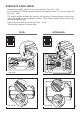
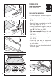
MODELS WITH WIRE RACKS
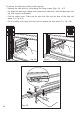
– Assemble the wire racks to the oven walls using the 2 screws (Fig. 4.2a - 4.2b).
In the models with catalytic panels interpose the catalytic panels “A” with the arrow up
(fig. 4.2a - 4.2b).
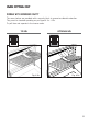
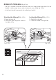
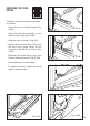
– Slide in, on the guides, the shelf and the tray (fig. 4.3a - 4.3b).
The shelf must be fitted so that the safety catch, which stops it sliding out, faces the
inside of the oven.
– To dismantle, operate in reverse order.