fw951 Integrated Frost Free Fridge Freezer Manual for Installation, Use and Maintenance Customer Care Department • The Group Ltd. • Harby Road • Langar • Nottinghamshire • NG13 9HY T : 01949 862 012 F : 01949 862 003 E : customer.care@cda.eu W : www.cda.
Important The CDA Group Ltd cannot be held responsible for injuries or losses caused by incorrect use or installation of this product. Please note that CDA reserve the right to invalidate the guarantee supplied with this product following incorrect installation or misuse of the appliance.
compliance with safety requirements of EEC Directive 2006/95/EEC (Low voltage) and requirements of EMC Directive 2004/108/EEC. This appliance has been manufactured to the strictest standards and complies with all applicable legislation, including Electrical safety (LVD) and Electromagnetic interference compatibility (EMC). Parts intended to come into contact with food conform to EEC/89/109.4 IMPORTANT INFORMATION FOR CORRECT DISPOSAL OF THE PRODUCT IN ACCORDANCE WITH EC DIRECTIVE 2002/96/EC.
Important Never store inflammable or explosive items and strong corrosive acids or alkalis in the appliance. This is a household appliance, which is produced in accordance with the national standard. It is intended for food storage only, not for storage of blood, medicine and biological products. To prevent risk of fire, keep the appliance away from petrol or any other inflammables.
Before First Use You must allow the fridge to settle for at least twenty four hours prior to switching the power on. It is recommended that you clean the interior of the appliance prior to first use, using a solution of bicarbonate of soda and warm water and then thoroughly drying the interior. The fridge may have an odour to it at first use. This will disappear as the appliance cools. Please note: The appliance will work continuously until it comes down to the correct temperature.
Use Fridge • Never put liquids in the refrigerator uncovered. • Never put hot foods in the refrigerator. Warm food should be allowed to cool to room temperature before being put into the refrigerator. • Nothing should rest against the rear wall of the refrigerator, as this will cause frost and possible condensation problems which will be difficult to remove. • Make sure food is clean and any extra water is wiped away before putting into the fridge.
• Follow the instructions on the food packaging for storage of frozen food. If no information is provided, foods should not be stored for more than three months after the purchase date. • Store food in small packages (ideally less than 2.5kg). This reduces the freezing time and improves the quality of the food after thawing. • Wrap food before putting into the freezer. To stop the wrapping sticking together, ensure it is dry.
Storage The fridge section is for short term food storage. Although the temperature can be maintained between 0-10˚C, extended periods of food storage is not recommended. 1 As the cold air circulates within the fridge, the temperature can vary between the different sections. As such, foods should be stored in different sections according to type. Section 6 is the coldest part of the fridge. 4 5 2 6 3 7 fig. 1 1. Butter 2. Food in jars and bottles 3. Drinks , e.g. milk 4. Cooked food 5.
To move the shelf, lift up the front section and then pull it outwards. To replace, slide the shelf back into the slot, and the lower the front section. The salad crisper is designed with a humidity control to ensure fruit and vegetables last longer. This can be adjusted by the slider at the front right of the salad crisper.
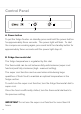
Control Panel C A Mid REF . High FRZ. Low S.Cool fig. 3 Mid High Low S.Cool B A. Power button To put the fridge freezer on standby press and hold the power button for approximately three seconds. The power light will flash. To start the compressor working again, press and hold the standby button for approximately three seconds until the power light stays lit. B. Fridge thermostat dial The fridge temperature is regulated by this dial.
C. Freezer thermostat dial The freezer temperature is regulated by this dial. The thermostat can be set between fully anticlockwise (super freeze function) and fully clockwise (high - warmest setting). The super freeze function can be used to freeze large quantities of fresh food as quickly as possible. To switch on the super freeze function, turn the freezer thermostat dial to super freeze. Once the food is frozen, turn the thermostat dial back to the previous setting.
Care and Cleaning Always disconnect the appliance from the power supply before any cleaning or maintenance. Both fridge and freezer are frost free and as such this appliance is designed not to require defrosting. The fridge and freezer sections should be cleaned using a solution of bicarbonate of soda and lukewarm water. Do not use abrasive products or detergents. After washing, rinse and dry thoroughly. Clean the shelves and balconies separately by hand with soap and water.
Defrosting the Fridge The fridge is cooled by convection using cold air forced through channels at the rear of the fridge. No defrosting is required. Defrosting the Freezer The freezer is frost free and as such is designed not to require defrosting. To switch off the compressor for a short period of time and so to force a defrost cycle, push and hold the Audio Alert Release / Force Defrost button for approximately five seconds. After 20 seconds, the defrosting process will begin.
Troubleshooting If you have any problems with your appliance, you should check the troubleshooting prior to calling CDA Customer Care to prevent unnecessary service calls and potential cost. If the appliance is not working • Check there is power to the appliance. • The power button on the control panel is switched on. • The house fuses are intact and the fuse in the plug has not blown. • The thermostat is not set to off. • The plug socket is functioning fine.
• T he cooling gas in the refrigerator will make a slight bubbling noise, even when the compressor is not running. Please note: The LED lighting cannot be replaced without a service call. If the light fails, contact CDA Customer Care. 560-570 Installation This appliance must never be installed close to heat sources, e.g. heating elements, cookers or in damp places. 540 50 17761782 808 67 808 • The cooling system at the rear of the appliance must not touch the rear wall.
Ventilation The main consideration when installing any refrigeration unit into a fitted kitchen is ventilation. The heat removed from the cooling compartment needs to be dissipated into the atmosphere. Incorrect ventilation can lead to premature compressor failure, excessive power consumption and total system failure.
Important Please follow the instructions to install this unit. The open channel at the rear is clearly shown. For the correct operation of the appliance it is important that the top of the housing unit is not blocked off. A channel depth of 40-50mm is normal with most units. A hole is shown in the base shelf of the unit; this allows air to be drawn over the compressor & heat exchange. Some installers fit a decorative plinth vent. In most cases this is not required, but is a welcome aesthetic addition.
Fitting the Product Into the Cabinet 1. R emove the gasket protection pieces: The gasket protectors prevent excessive seal compression during transport and are required during the installation process. Remove the gasket protector from each door (fig 6) and proceed with the installation. Cover caps are provided to fill the hole; take care when inserting these. 2.
top edge of the product (fig.7) (b). The trim piece should be fitted loosely at this stage to allow access to the top fixing brackets. 4. Fitting the magnetic seal strips: Two magnetic seals are supplied to fill the gap between the cabinet and the edge of the products. These simply fit against the left and right edges. To make it easier, it is useful to apply a little sticky tape to the top and bottom of each strip to prevent curling. Note that the seal may need to be cut to length. 5.
8. Fitting the bottom cabinet fixing bracket: sliding bracket is provided to A secure the non-hinge side of the product to the cabinet. This is fitted to the bottom of the product using two machine screws, as shown below. A guide piece is also provided to ensure the unit is aligned when installed. Fit the bracket and guide, as shown but do not tighten the securing screws to allow the bracket to slide left and right. Guide piece simply slotted in to the fixing bracket fig. 10 fig.
At this stage ensure that the product is centrally aligned within the housing and then remove the guide pieces from the hinges. 10. Securing the product to the housing: Secure the product to the housing at the hinge side by using two screws in each hinge. The fixing holes in each hinge as shown in figure 10. 11.
Fitting the Cabinet Fascia Doors First, fit the upper fascia by following the steps below. After fitting the upper fascia in the correct position, use the lower edge of the upper fascia as a guide for positioning the lower fascia (A distance between the two fascias when installed is normally between 2 and 4mm) and fit the lower fascia. 1. With the door open and using the fitting guides, position the door in the required position with respect to the cabinet (figure 14). 2.
of appropriate length. Please take care to ensure the screws selected will not punch through the fascia door. Under end face of fascia 4. Remove the fitting guides. 5. Attach the fascia door assembly to the refrigerator (onto the height adjustment screws) and loosely fit the securing nuts. At this stage the final vertical and horizontal position of the fascia assembly may need adjustment (figure 17). Fitting guides fig. 19 6.
Adjusting the Position of the Fascia Doors The position of the fascia doors can be made in all 3 axes by following the guide shown below (figure 20). If the range of adjustment detailed below is not enough then the refrigerator is not located correctly in the cabinet and/ or the upper fascia fixing plates are incorrectly positioned. Horizontal Adjustment (Y): 1. Loosen the upper fixing plate nuts (B). 2. Slide the plate left or right as required; this gives approximately 5mm of adjustment. 3.
Depth Adjustment (Z): Ensure that the vertical and horizontal positions are correct before adjusting the depth. 1. Loosen the depth adjustment screw (C). 2. Move the fascia in or out, as required; this gives an adjustment of approximately 3mm. the lower fascia brackets are slotted to allow alignment of the fascia at the bottom. This is shown in figure 22.
Fitting the Trims and Cover Pieces 1. Open the door and lift out the decorative covers (marked ‘a’) in figure 20 fig. 23 2. Remove the position guides (d), turn them round so that the lip at the top faces outwards and insert them into the slots shown in the image (e); these will be used to line up the fascia panels before securing them in position. 3.
400. Secure the mounting bracket to the fascia panel using the provided wood screws, ensuring that the screws will not penetrate through the fascia where there are any rebates, etc. and then remove the guides. Any small errors, as in the image above, can be adjusted for after the fascia has been mounted. 5. Hang the fascia panel on the support pins and check that the fascia is positioned correctly. Adjustments can be made in all directions at this stage using the adjustment points shown in figure 26.
Electrical Information Warning! This appliance must be earthed. Green and Yellow to Earth A 13 Amp Brown to Liv e B 13 Amp fuse Cord Clamp fig. 28 Blue to Neutra l The mains lead of this appliance has been fitted with a BS 1363A 13 amp fused plug. To change a fuse in this type of plug, follow the steps below: 1. Remove the fuse cover and fuse. 2. Fit replacement 13A fuse, ASTA approved to BS 1362 type, into the fuse cover. 3. Replace fuse cover.
As the colours of the wires in the mains lead of this appliance may not correspond with the coloured markings identifying the terminals in your plug, proceed as follows:• The wire which is coloured GREEN and YELLOW must be connected to the terminal which is marked with the letter (E) or by the Earth symbol or coloured GREEN and YELLOW. • The wire which is coloured BLUE must be connected to the terminal which is marked with the letter (N) or coloured BLACK.
Please contact our Customer Care Department for Service on the details below Customer Care Department • The Group Ltd. • Harby Road • Langar • Nottinghamshire • NG13 9HY T : 01949 862 012 F : 01949 862 003 E : customer.care@cda.eu W : www.cda.