HG3601FR - HG3602FR Domino Cooking Hobs Manual for Installation, Use and Maintenance GB Customer Care Department • The Group Ltd. • Harby Road • Langar • Nottinghamshire • NG13 9HY T : 01949 862 012 F : 01949 862 003 E : service@cda.eu W : www.cda.
Important This appliance is designed and manufactured solely for the cooking of domestic (household) food and is not suitable for any non domestic application and therefore should not be used in a commercial environment. The appliance guarantee will be void if the appliance is used within a non domestic environment i.e. a semi commercial, commercial or communal environment.
Important Safeguards and Recommendations – Do not carry out any cleaning or maintenance without first disconnecting the appliance from the electrical supply. – During and after use of the hob, certain parts will become very hot. Do not touch hot parts. – After use always ensure that the control knobs are in the “●” OFF position. – Young children should be supervised to ensure that they do not play with the appliance. – Keep children away from the hob during use.
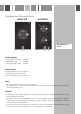
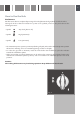
Features and Technical Data HG3601FR HG3602FR 2 1 3 This appliance is class 3 Fig. 1a 4 Fig. 1b 5 6 Cooking Points 1. Triple ring burner (TR) - 3,50 kW 2. Rapid burner (R) - 3,00 kW 3. Semi-rapid burner (SR) - 1,75 kW Control Panel 4. Triple ring burner (1) control knob 5. Rapid burner (2) control knob 6. Semi-rapid burner (3) control knob Note: – The electric ignition is incorporated in the knobs. – The appliance has a safety valve system fitted.
How to Use the Hob Gas Burners Gas flow to the burners is adjusted by turning the knobs (illustrated in fig.2) which control the valves.
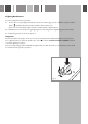
Lighting Gas Burners In order to light the burner, you must: 1 – Press in the corresponding knob and turn counter-clockwise (fig. 3) to the full flame position marked by the symbol and hold the knob in until the flame has been lit. In the case of a mains failure light the burner with a match or lighted taper. 2 – Wait about ten seconds after the gas lighting before releasing the knob (starting time for the valve). 3 – Adjust the gas valve to the desired power.
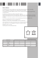
Choice of Burner The symbols printed on the panel by the side of the knob indicate which burner you are controlling. Choose a suitable burner depending on the cookware diameter and capacity. The pan diameter should be suitable for the burner power to make the most of the burner's high efficiency and not waste fuel. A small pan does not boil more quickly on a large burner (fig. 4).
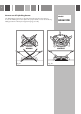
Correct use of Triple-Ring Burner The flat-bottomed pans are to be placed directly onto the pan-support. To use the WOK you need to place the proper stand in order to avoid any faulty operation of the triple-ring burner (Figs. 5a - 5b). WRONG Fig. 5a Model: HG3601FR CORRECT Fig.
Fig. 6 Fig.
Cleaning and Maintenance General Tips – Before cleaning the hob switch it off and wait for it to cool down. – Clean with a cloth, hot water and soap or liquid detergent. – Do not use products which are abrasive, corrosive or chlorine based. – Do not use steel pads. – Avoid using cleaning products with a chlorine or acidic base. – Do not leave acid or alkaline substances (vinegar, salt, lemon juice, etc.) on the hob. – Steam cleaners must not be used when cleaning this appliance.
Burners and Grids – These parts can be removed and cleaned with appropriate products. – After cleaning, the burners and their flame spreaders must be well dried and correctly replaced. – It is very important to check that the burner flame spreader and the cap have been correctly positioned. Failure to do so can cause serious problems. – Check that the electrode S (figs. 9 and 13) is always clean to ensure trouble-free sparking. – Check that the probe T (figs.
Correct Position of Triple Ring Burner The triple ring burner must be correctly positioned (see fig. 9); the burner ribs must be fitted in their housing as shown by the arrow. The burner correctly positioned must not rotate (fig. 10). Then position the cap A and the ring B (figs. 10 - 11). The pan support shall be correctly positioned as indicated in fig. 12. The pan support shall be level and must not rotate. Model: HG3601FR Fig. 11 Ignitor “S” Sensor “T” Fig. 9 A Fig. 10 B Fig.
Correct Positioning of the Semi-rapid and Rapid Burners – It is very important to check that the burner flame spreader F and the cap C have been correctly positioned (see figs. 13 and 14). They shall be level and must not rotate. Failure to do so can cause serious problems. – The pan supports shall be correctly positioned as indicated in fig. 15. The pan supports shall be level and must not rotate. Fig. 14 C F Ignitor “S” Fig. 13 Sensor “T” Fig.
TIPS FOR INSTALLATION Location – The appliance may be installed in a kitchen, Kitchen/diner or a bed sitting room, but not in a room or space containing a bath or a shower. – The appliance must not be installed in a bed-sit room of less than 20m3. – The appliance is designed and approved for domestic use only and should not be installed in a commercial, semi commercial or communal environment.
Installation Technical Information for the Installer HG3601FR 300 49 0 52 (1) 50 (2 ) 0 51 270 HG3602FR 300 50 (2 ) 0 51 49 0 52 (1) In order to install the hob into the kitchen fixture, a hole with the dimensions shown in fig. 16 has to be made, bearing in mind the following: – Within the unit, between the bottom of the hob and the upper surface of a shelf there must be a clearance of at least 30mm.
Fastening the Cooktop Each cooktop is provided with an installation kit including brackets and screws for fastening the cooktop to benches from 30 to 40 mm thick.The kit includes four R brackets and four self-threading screws S (figs. 19, 20). – Cut the unit according to the dimensions in fig. 16. – Turn the hob upside down and rest the glass side on a soft surface. – Spread the seal G around the edge of the hob (fig. 19).
Gas Supply Requirements Important Note This appliance is supplied for use on NATURAL GAS or LPG (check the gas regulation label attached on the appliance). – Appliances supplied for use on NATURAL GAS: they are adjusted for this gas only and cannot be used on any other gas (LPG) without modification. The appliances are manufactured for conversion to LPG. – Appliances supplied for use on LPG: they are adjusted for this gas only and cannot be used on any other gas (NATURAL GAS) without modification.
Gas Connection The installation of the gas appliance to Natural Gas or LP Gas must be carried out by a suitably qualified and registered installer. Installers shall take due account of the provisions of the relevant British Standards Code of Practice, the Gas Safety Regulations and the Building Standards (Scotland) (Consolidation) Regulations issued by the Scottish Development Department. Installation to Natural Gas Installation to Natural Gas must conform to the Code of Practice, etc.
Gas connection Cat: II 2H3+ The fitting (fig. 21) is made up of: – 1 nut A – 1 elbow fitting C – gasket F Connection to the Gas Supply – Be careful when flexible pipes are used that they do not come into contact with moving parts. – To maintain the thickness of 3 cm, the hob is fitted with a channel to contain the connection pipe. – The gas inlet union can be turned in the direction required after the elbow fitting C and nut A connection (figure 21) has been slackened (fig. 22).
Conversion to Natural Gas or LPG Replacing the Burner Injectors If the NATURAL GAS/LPG conversion kit is not supplied with the appliance this kit can be purchased by contacting the After-Sales Service. Choose the injectors to be replaced according to the table below. The injector diameter, expressed in hundredths of a millimetre, is marked on the injector body. To replace the injectors proceed as follows: – Remove the pan supports, the burner caps and flame speaders.
Regulating the Burner Minimum Setting When changing from one type of gas to another, the minimum tap output must also be correct, considering that in this position the flame must be about 4 mm long and must remain lit even when the knob is turned sharply from the maximum to the minimum position. The adjustment is performed with the burner lit, as follows: – Turn the knob to the minimum position. – Remove the tap knob. – Turn the screw A to the correct setting with a screwdriver (fig. 25).
Mains Electricity Connection Incorrect installation may be dangerous and the manufacturer can not be held responsible. Warning! This appliance must be earthed The manufacturer declines all responsibility for any problem caused by failure to observe this rule. THIS APPLIANCE MUST BE CONNECTED TO THE MAINS SUPPLY BY A COMPETENT PERSON, USING FIXED WIRING VIA A DOUBLE POLE SWITCHED FUSE SPUR OUTLET AND PROTECTED BY A 3A FUSE.
Appliance Servicing CDA provide a quality and effective after-sales service to cover all your servicing needs. Please attach your receipt to this page for safekeeping. Please help us to help you by having the following information available when booking a service-call: 1. Model type, make and model – see the product data plate. 2. Evidence of installation / purchase date 3. Retailer where appliance was purchased 4. Clear and concise details of the fault 5.
Cod. 1104561 - ß2 To contact our Customer Care Department, or for Service, please contact us on the details below. Customer Care Department • The Group Ltd. • Harby Road • Langar • Nottinghamshire • NG13 9HY T : 01949 862 012 F : 01949 862 003 E : service@cda.eu W : www.cda.