PC40 240 VAC Pattern Control Part 108 3898 NORDSON CORPORATION • AMHERST, OHIO • USA
Nordson Corporation welcomes requests for infonnation, comments and inquiries about its products. Address all correspondence to Nordson Corporation 11475 Lakefield Drive Duluth, GA30136 Notice This is a Nordson Corporation publication which is protected by copyright. Original copyright date 1993. No part of this document may be photocopied, reproduced, or translated to another language without the prior written consent of Nordson Corporation.
0-1 Table of Contents Table of Contents Section 1 Safety Summary Section2 Equipment Familiarization 1. Introduction . . . . . . . . . . . . . . • . . . . . . . . . . . . . . . . . . . . . . . . . 1-1 2. Explanation of tenns and symbols . . • . . . . . . . . . . . . . . . . . . . . 1-1 3. Safety during installation . . . . . . . . . . . . . . . . . • . . . . . . . . . . . . 1-2 1. Introduction . . . . . . . . . . . . . . . . . . . . . . . . . . . . . . . . . . . . . . . . 2-1 2.
0-2 Table of Contents 9. PC40 Remote Communications Installation . . . . . ........... Remote Pin Characterization •• •.•... . .... . . .. . ..... .. . Remote Memory Selection and Memory Logic •........ .. . Remote Memory Select Switch lnstarration .. .. .. .. .. .. .. . Keyed Lock Out Switch Installation . .. . ... . .... . ... ... .. Sectlon4 Operating Instructions 3-24 3-24 3-25 3-25 3-29 1. Introduction .... .. . .. •... . .. ... ... . . •.. .. .. ...... .... 4-1 2. PC40 Parameters Overview . .. .
0·3 Table of Contents 7. Configure Mode ..•... •.... ..•.......... ... . . . . ...... Purpose . . . . . . . . . . . . . . . . . . • . • . . . . . . . . . . . . . . . . . . . . • Accessing Configure Mode •.. . .... . .•.. . . . . ... . . . . . .. Changing Selection Levels . . . . • . . . . . . . . . . . . . . . . . . . . . . Exiting Configure ... .... ..... . •..... . ... . .. . . . . . . . . . Selecting Available Parameters ..... . . . .... ... . . . ... . . . 8. Test Mode ......... .. .. ... . .... .....
Section 1 Safety Summary C N01<1son Corpora~on 1993 AI Roghts Res.,...
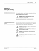
1-1 Safety Summary Section 1 Safety Summary 1./ntroduction Section 1 of the applicator manual includes safety guidelines for the use of Nordson equipment. These guidelines apply to all operators and service personnel working with the PC40. • WARNING: Allow only qualified personnel to perform installation and troubleshooting . In addition to the safety information in the technical manuals, follow the specific safety precautions contained in this manual. 2.
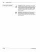
1-2 Safety Summary 3. Safety During Installation WARNING: Risk of serious personal injury or death. Failure to follow the safety and operation information in the technical manuals for the applicator and its associated equipment can result in personal injury or death. Before installing, servicing, or operating the PC40, thoroughly review Section 1, Safety Summary, in the applicator and its associated equipment technical manuals. WARNING: Risk of electrocution.
Section 2 Equipment Familiarization c Norc!son Corpornon 1993 AI Rights Reserved P/N 101138911.
Equipment Familiarization 2-1 Section 2 Equipment Familiarization 1. Introduction The Nordson~ PC40 Pattern Control (Figure 2.1) is a time-based control that makes it possible for you to quickly and easily set up, select, or change material application patterns. The PC40 is designed for applications in which material is applied to substrates moving at a constant line speed.
2-2 Equipment Familiarization NOTE: The PC40 240 VAC Pattern Control is designed for use only in geographic regions where 240 VAC with a grounded neutral is the industrial standard. If 120 VAC with a grounded neutral is the industrial standard at your site, consider using either the PC40 AC Pattern Control (P/N 131 712), or the PC40 DC Pattern Control (P/N 131 709) and PS40 DC Power Supply (P/N 131 739). NOTE: The PC40 240 VAC Pattern Control uses 220/240 VAC solenoids to actuate pneumatic guns.
Equipment Familiarization 2·3 4-- B 1-~----- I [ID---' l ro I I c -- s-- Jrr=r-· ~s= I I G I -- I \ I I F --2 Figure 2.
2-4 Equipment Familiarization 3. PC40 User Interface The PC40 front panel (Figure 2.3) consists of an LCD, nine indicator LEOs, six membrane push buttons, a power switch and a fuse. PC40 15 LOCK CONFIOUAE 1 PROOIIA._. RIM TEST 1-----~ MEMORY . CHANNEL 1--------1 14 ..... f. .. -··. 1 2 .•, 3 · 13 :_~ ·. .· ' I 2 3 4 C> 10 5 6 7 9 8 Figure 2.
Equipment Familiarization LCD 2-5 Blue alphanumeric characters are displayed against a gray background (Figure 2.4) . NOTE: Rgure 2.4 is for familiarization only; these symbols are never all displayed at the same time. 1 14 nnnn uuuu ---- 13 12 2 c D 3 10 4 3 • 4 6 Figure 2.
2-6 Equipment Familiarization 4. Nordson Photoelectric Sensors There are four photoelectric sensors that are available from Nordson for use as trigger devices with the PC40: • (1) Opposed Mode (Through Beam) Sensor, which consists of an Emitter and a Receiver • (1) Diffuse Reflective (Proximity) Sensor • (2) Retroreflective Sensors Opposed Mode (Through Beam) Sensor This sensor consists of two units: an LED light source {emitter) mounted· opposite a light-sensing phototransistor (receiver) .
2-7 Equipment Familiarization Retroreflectlve Sensors This sensor consists of a single unit that contains the LED light source (emitter) and the light-sensing phototransistor (receiver). The emitter/receiver bounces its light off an opposing retroreflector or reflective tape and "sees" the reflected light. The light beam is broken as the substrate passes between the sensor unit and the reflector (Figure 2.7). Figure 2.
2·8 Equipment Familiarization 5. Remote Communications Remote Memory Selection Purpose The PC40 has the capability to connect to a remote device which can change the active memory. The unit can also provide +12V power for the remote device. Wiring information for the Nordson Remote Memory Select Switch is included in Section 3, Installation. Remote Lock Out Interface Purpose The PC40 will prevent access to the PROGRAM, CONFIGURE, and TEST modes after receiving an input signal from a remote device.
Section 3 Installation Cl Nocdson Corporation 1993 AI Roghts Reserved PIN 108389.4.
3-1 Installation Section 3 Installation 1. Introduction This chagter includes information on inspe~ing and i_nstalling the Nordson PC40 Pattern Control and assoc1ated equ1pment: • the gun solenoids, • the Nordson Sensors, • the Nordson Remote Memory Select Switch, and • the Nordson Keyed Lock Out Switch. 2. Inspection After unpacking, check that you have the pattern control and other equipment that you ordered (see Section 6 for part number information).
3-2 Installation Avoiding Inductive Interference (Electrical Noise) • Avoid routing wires near AC power lines, solenoid output lines, and electrical devices such as motors, contactors; and relays. • Use shielded cable. • Avoid using excess wire lengths, which can act as an antenna. Use only as much wire as needed to make connections. limit Switches ·(it used) • Limit switches should be wnormally closed." This will provide a stable sensor signal. • Limit switches can bounce when actuated.
3-3 Installation Wall or Machine Mounting (continued) Figure 3. 1 • Removing the PC40 front assembly 1 - Back enclosure 2- Front assembly 3 - Screw {1 of 6) DIN Rail Mounting NOTE: Before mounting the PC40, make sure that you have sufficient space to mount it. The unit is 4.0 in. w ide (10.2 em) by 9 .0 in. high (22.9 em) by 4.44 in. deep (11 .3 em). Use the parts provided with the PC40 (Figure 3.3) to install the unit to DIN rails as follows: Mounting to Vertical Ralls 1.
3-4 Installation DIN Rail Mounting (continued) T l A Figure 3.2 - Mounting PG40 to wall or machine surface A - 6 in. (15.2 em) 1 - Back enclosure 2- Screw with washer (nut not shown); 1 of 2 2. Use the two M4 x 12 mm screws to secure the two clips to the back enclosure; make sure that they are oriented for mounting to the vertical rail (Figure 3.3). 3. Fasten the back enclosure to the DIN rail by snapping the clips into the rail. p"" 108 389A 57.28 1,'g3 C Nordson Corpora1.,n 1993 All Rogllts Res.
Installation 3-5 DIN Rail Mounting (continued) 6 4 Figure 3.3- Mounting PC40 to vertical DIN rails 1 - Clip (1 of 2) 2 - Back enclosure 3 -Screw with washer (1 of 2) 4 -Stop screw 5- End bracket 6-DIN rail o NOtdson Corporabon 1993 IIJ1 Rtghts ReseJVed PIN 106 389.
3-6 Installation Mounting to Horizontal Ralls DIN Rail Mounting (continued) Make sure that the rails are 6.0 in. (15.24 em) apart from center to center. Also make sure that the DIN rails are at least 4.0 in. (1 0.2 em) in length. 1. Use the two M4 x 12 mm screws to secure the two clips to the back enclosure; make sure that they are oriented for mounting to the horizontal rails (Figure 3.4). 1 ~~'~?T 2 6.0" ~=========(~15J[cm) '8,, 4 Figure 3.
3-7 Installation 6. PC40 Electrical Connections WARNING: Risk of electrocution. The PC40 240 VAC Pattern Control can only be used in geographic regions where 240 VAC with a grounded neutral is the industrial standard. Failure to connect the unit to a grounded neutral can result in personal injury or death.
3-8 Installation Connecting AC Power to the PC40 ACUnit c. Rotate the front assembly 180" (Figure 3.6). (continued) Figure 3.6 - Rotating the front assembly PIN 108389A 57-28 1/93 C Nordson Corporation 1993 All R.
3-9 Installation Connecting AC Power to the PC40ACUnit d. Push the two screws through the top two front assembly holes (Figure 3.7, view A). (continued) e. Insert the screws into the two back enclosure stand-offs (Figure 3.7, view A). f. lighten the two screws to secure the front assembly to the back enclosure (Figure 3.7, view 8). A B Figure 3.
3-1 0 Installation Connecting AC Power to the PC40AC Unit WARNING: Risk of electrocution. The AC input power line to the PC40 provides voltage that can cause personal injury or death. Before making any electrical connecti ons, disconnect and lock out power to the main circuit breaker for the input power line (Figure 3 .8}. (cootinued) WARNING: Shock hazard. Touching bare wires in the PC40 can result in shock that can cause personal injury or death.
3-11 Installation Connecting AC Power to the PC40AC Unit 5. If you are connecting other devices at this time, proceed to the appropriate installation procedure(s) in this section. (continued) n. P2 P2-1 P2-2 P2- 3 P2- 4 P2- 5 P2- 6 P2-7 P2- B P2-9 P2-10 P2-11 P2-12 llr r-- & & & I & & & & & & & & & ....._ P1 P1-1 P 1-2 P1- 3 P1- 4 P 1-5 P1· 6 P1·7 P1· 8 p4 ....--- r-- & & & & & & & & & & & & & & & & '- '- P4-1 P4-2 P4·3 P4· 4 P4· 5 P4-6 P4-7 P4-B L/ 0 0 Figure 3.
3-12 Installation 7. Solenoid Wiring Installation Gun Solenoid Wiring NOTE: The PC40 240 VAC Pattern Control uses 220/240 VAC solenoids to actuate pneumatic guns. The unit should not be used to actuate electric gun drivers. If you are using electric gun drivers, order the PC40 DC Pattern Control (P/N 131 709) and PS40 DC Power Supply (PIN 131 739}. 1. Install the gun solenoid(s} following the instructions provided in the manual you received with your applicator. 2.
3-13 Installation Gun Solenoid Wiring (continued) ! WARNING: Burns. Unexpected gun firing can occur during PC40 installation. The firing can be a response to trigger signals caused by foreign objects blocking the sensors, and by intentional and unintentional triggering that can occur during maintenance. Nordson recommends that you install quick-disconnect solenoid leads. Disconnect the leads during installation to disable the solenoid.
3-14 /nstalfation 5. If you are NOT connecting other devices at this time, do the following: Gun Solenoid Wiring (ccntinued) a. Grasp the front assembly with one hand. Remove the two screws holding it to the back enclosure. b. Carefully rotate the front assembly enclosure. 1so• and place it on the back c. Replace and tighten the two loose screws. d. lighten the four remaining screws. 6.
Installation Current Sinking (NPN) Requirements 3-15 A current sinking (NPN) device capable of sinking at least 10 rnA must be used to stimulate the signal inputs. The internal circuitry for the Nordson photosensor is pre-wired to include the required NPN switching element. Figure 3.10 shows the wiring diagram for the Nordson photosensor. B - 8 1 IIIII k A II Ill 2 3 4 ! t"" ~ I I ~ T - * ~ 7 Figure 3.
3-16 Installation Tips for Minimizing Unwanted Triggering • Mount the sensor to metal that is connected to earth safety ground (system ground). (continued) • Adjust photosensor gain to the minimum required sensitivity. This will reduce both electrical and optical problems. • The photosensor cable shield should be grounded at both ends. This will reduce the effects of electrical noise produced by contactors, motors, and arc-welders.
3-17 Installation Mounting Dimensions (continued) Figure 3. 12 - Sensor bracket dimensions 1-0. 10 in. (2.5 mm) 2 - 0. 79 in. (20. 1 mm) 3- 1.79 in. (45.5 mm) 4 - 90 degrees 5 - 0.80 in. (20.3 mm) 6 - 10 degrees (typically) Mounting Nordson Sensors 7- 0. 170 in. (4.3 mm); 2 slots 8 - 1.25 in. (31.8 mm) 9- 15 degrees (either direction) 10-0. 120 in. (3. 1 mm) 11 - 0.120 in. (3.1 mm) 1.
3-18 Installation Mounting Nordson Sensors (continued) 3. Locate the sensor bracket so that the sensor Is no closer than 2 in. (5.1 em) nor further than 15 in. (38.1 em) from the substrate. 4. Securely connect the sensor bracket to the mounting surface. Excessive movement or vibration can result in intermittent or false operation caused by loss of alignment to the substrate. 5. Using the two mounting bolts provided with the sensor bracket, secure the sensor to the bracket (Figure 3.13). Figure 3.
3-19 Installation Mounting Nordson Sensors Mounting Opposed Sensors (continued) NOTE: To avoid unwanted trigger signals, make sure that there are no objects other than the substrate that pass between the emitter and receiver during line operation. Also, make sure that the emitter and receiver are mounted no more than 10ft (3 m) from each other. 1. Check the intended mounting position to ensure that there is enough space to mount the sensor(s} and bracket(s}. See Figure 3.11, Figure 3 .12, and Figure 3.
3-20 Installation Mounting Nordson Sensors Mounting Retroreflectlve Sensors (continued) NOTE: To avoid unwanted trigger signals, make sure that there are no objects other than the substrate that pass between the emitter/receiver and the reflector during line operation. NOTE: Make sure that the emitter/receiver and reflector are mounted no more than 7 ft (2.13 m) from each other {polarized model) or no more than 15ft {4.5 m) from each other {non-polarized model). 1.
Installation Nordson Photosensor Wiring Connections 3-21 WARNING: Risk of electrocution. The AC input power line to the PC40 provides voltage that can cause personal injury or death. Before making any electrical connections, disconnect and lock out power to the main circuit breaker for the input power line (see Figure 3.8). 1. Connect the wires for each photosensor as indicated in Table 3.7 or Table 3.8. See Figure 3.9 for the location of terminal block P4. Table 3.
3·22 Installation Alignment Indicator Aligning Sensors Nordson photosensors have an alignment indicator (LED) . The LED pulse (flash) rate increases as alignment improves. The sensor is adjusted so that the LED is off (not flashing) in the dark condition or is on (flashing) at a fast rate in the light condition. The LED flash rate also indicates when sensor maintenance is needed. Whenever the flash rate is slow, the sensor's lenses should be cleaned and the alignment checked.
3-23 Installation Aligning Sensors Aligning Opposed (Through Beam) Sensors (continued) 1. Remove the gasketed acrylic cover located above the sensor electrical cable. 2. Turn on power to the sensor. 3. Direct the emitter at the receiver and observe the red alignment LED on the receiver (Figure 3.14). 4. Turn the gain control to the fully clockwise position. The LED should be flashing on and off. 5. Adjust the position of the emitter and/or receiver to achieve the maximum alignment LED flash rate. 6.
3-24 Installation 9. PC40 Remote Communications Installation The following information is provided if you will be using a remote device to select active memory and/or lock out input through the PC40 user interface. Remote connections are made to PC40 terminal block P1 (Figure 3.9) . Signals connected to P1 are optically isolated from the remote system. The opto-isolators can be turned on by either current sourcing or current sinking devices.
3·25 Installation Remote Memory Selection and Memory Logic The logic levels should be held continuously. Remote selection will take place after the levels have been there for at least 500 ms. If you try to select a non-configured memory, the current memory remains in effect and the PC40 status LED will light red. The LED will stay on until you select a configured memory or configure the memory you were attempting to select.
3-26 Installation Remote Memory Select Switch Installation f. lighten the two screws to secure the front assembly to the back enclosure (Figure 3.7, View B). (continued) WARNING: Risk of electrocution. The AC input power line to the PC40 240 VAC power supply) provides voltage that can cause personal injury or death. Before making any electrical connections, disconnect and lock out power to the main circuit breaker for the input power line (see Figure 3.8). WARNING: Shock hazard.
Installation Remote Memory Select Switch Installation (continued) 3-27 NOTE: When both the Rotary Select Switch and Keyed Lock Out Switch are installed, both must be connected as either sourcing devices or as sinking devices. Figure 3.16 shows the wiring for the Rotary Select Switch as a sourcing device. Figure 3.17 shows the wiring for the switch as a sinking device. 4.
3-28 Installation Remote Memory Select Switch Installation Switch Used as a Sinking Device (continued) Use an 18-22 gauge wire (customer supplied) to make the connections shown in Figure 3.17. Make sure to install the jumper from PC40 connection P1 -3 to P1-8. A c Figure 3. 17 - Current sinking remote memory switch (rear view) A - P1-2 (Groundj; also, install jumper from PC40 connection P1-3 to P1-8 8- P1 -7 ("Remote Memory Select 1? C- P1-6 ("Remote Memory Select 2j D.
3-29 Installation Keyed Lock Out Switch Installation NOTE: This switch is not intended to be installed in the PC40. It can be mounted on a remote panel, etc. The Nordson Keyed Lock Out Switch is an A-lock type, 4-tumbler switch that prevents any input via the PC40 user interface. NOTE: When both the Keyed Lock Out Switch and Rotary Select Switch are installed, both must be connected as either sourcing devices or as sinking devices. Figure 3.
3-30 Installation Keyed Lock Out Switch Installation 3. Use 18-22 gauge wire (customer supplied) to make the switch and PC40 jumper wire connections by doing one of the following (ccntinued) • Switch Used as a Sourcing Device - Use an 18-22 gauge wire {customer supplied) to make the connections shown in Figure 3.1 8. Make sure to install the jumper from PC40 connection P1-2 to P1-3. 0 A P1 P1-1 P1-2 P1-3 P1-4 P1-5 P1-6 P1·7 P1-8 ~---------+4------8 0 0 Figure 3.
Installation Keyed Lock Out Switch Installation 3-31 • Switch Used as a Sinking Device - Use an 18-22 gauge wire (customer supplied) to make the connections shown in Figure 3.19. Make sure to install the jumper from PC40 connection P1-3 to P1 -8. (continued) 0 A P1-1 P1-2 P1-3 P1-4 P1-5 P1·6 P1-7 P1·8 0 B Figure 3.
3-32 Installation Keyed Lock Out Switch Installation 4. If you are NOT connecting other devices at this time, do the following: (continued) a. Grasp the front assembly with one hand. Remove the two screws holding it to the back enclosure. b. Carefully rotate the front assembly enclosure. 1ao• and place it on the back c. Replace and tighten the two loose screws. d. Tighten the four remaining screws. 5.
Section 4 Operating Instructions 0 NO
4-1 Operating Instructions Section 4 Operating Instructions 1./ntroduction Through descriptions and examples, this section will provide the tools that will help you identify what patterns you want and how to get those patterns. · In "PC40 Parameters Overview~ we will define the terminology associated with pattern control and identify the decision factors that you will consider when setting up your application pattern.
4-2 Operating Instructions 2. PC40 Parameters Overview Parameters are the choices and values that you have to program into the PC40. These choices and values, when properly set, will give you the material bead pattern (s} you want on the substrate. The following paragraphs provide information on the different decisions involved in setting each parameter at each selection level. The initial display for each selection level is shown.
4-3 Operating Instructions Channel (continued) 1 ---- -- -- - Figure 4. 1 - Bead sequences 1 - Bead (gun on) Trigger 1 ~ 2 J ~ Symbol depicts sensor "off' to won" ~ xl Symbol depicts sensor "on" to "off' Definition: A device (e.g., photosensor) that senses the approach of a substrate and sends a trigger signal to the PC40.
4-4 Operating Instructions Trigger (continued) Table 4. 1 - Trigger Device Mode and Location, and Corresponding PC40 Edge Symbol Selection Dark Operate Mode <1> Ught Operate Mode <2> Leading Edge Leading Edge Trailing Edge Trailing Edge Opposed (ThroughBeam) (P/N 131 473 and 131 486) Retroreflective (P/N 131 474 or 131 475) Diffuse Reflective (Proximity) (P/N 131 476) Ill For diffuse reflective sensors, this is the preferred mode for minimizing false triggers.
4-5 Operating Instructions Transition X Definition: A change from one in.terval to the other: either a change from a delay to a duration or from a duration to a delay. The combination of delays and durations makes up a transition sequence (Figure 4.2). 2 Q I I I I· I· 1 0 A 3 - ~B~ - ..----4-- Figure 4.
4-6 Operating Instructions Transition In programming the PC40, the transition values refer to the end-point of each delay and each duration. Each end-point is defined in relation to the trigger signal, which is the starting point of the entire transition sequence. Each transition value is a distance measure that is converted to time values. (continued) NOTE: The initial delay for an application with a leading edge trigger has to account for the trigger to gun distance (A in Figure 4.
4-7 Operating Instructions IO Stitch Definition: • xl Material application with a duration that consists of a repeating pattern of short material beads (stitch lengths) with uniform spaces (stitch gaps) between them. Decision Factors: • material savings • pattern requirement In the stitch level, you can select a percentage of coverage and stitch bead length for a given duration.
4-8 Operating Instructions 3. Setting Up the Pattern Because the PC40 is digitally programmed, all pattern values can be calculated and programmed in advance. It may be helpful to draw a simple diagram of the pattern you want (like the one shown in Figure 4.5). Leave sufficient space on your diagram for recording trigger to gun and bead measurements. Measurements should be made in millimeters or inches. -- -- Figure 4.
4-9 Operating Instructions Example 1: Cartoning (One End Only) (continued) NOTE: The first delay measurement must include the gun to trigger distance (A) plus the distance from the edge of the substrate to the start of the first duration (B). 2 0 I I I I A~I I I T2 T1 Bl I 850 250 150-1100 I I I ,. ., 600 3 ..-- 4 I 1 T1 I I I ~ ~ ... T;s T2 I I -- I I I I li I T4 I I I r. . I t 7 5 ..·- - - - - 500 - l 7 5 75 1 225 300 BOO 875 t--4 3 ,._- -5- -Figure 4.
4-1 0 Operating Instructions Example 1: Cartoning (One End Only) (continued) Converting Distance Measurements to Tlme Values Each of the distances must be converted to time values. 1. Measure the conveyor fine speed. (l) • Metric: measure in meters per minute (m/min) • English: measure in feet per minute (ftlmin) 2. Use the appropriate formula to convert each measurement to a time value. (2) 0 ·06 ~ ~is~nce)mm) - Time in seconds me pee • Metric: • English: 5 x Distance {in.) Ti . d L.
Operating Instructions 4-11 Example 1: Cartoning (One End Only) (continued) Illustrated Pattern Parameters- Figure 4.7 shows the converted time values (transitions) for this example. Figure 4.8 shows how the parameters are recorded on the pattern log for this example. 2 Q 'I : T1 A-i 8I I 197 I 328 1116 ~ 131 141•--------788- -- -- --.-1•1 ... 3 ---4 1 T1 I T3 T2 I I -~,.,~ ...r.-·l. I I ' I I I I -I I I I ---i r. . I ·-----656 T4 295 393 I --4 98 1049 1147 3 ...,.
4-12 Operating Instructions Programming Decision Factors for This Example: Example 1: Cartoning (One End Only) {continued) Memory - One memory is needed. Memory 8 is circled on the pattern log, but any configured memory could be selected. Channel - Two channels are needed because: • Two gun solenoids are used (one for gun 1, and one for guns 2 and 3) . • There are two sets of transition values. Even though there are three bead sequences, the lower two have identical transition values.
4-13 Operating Instructions Example 2: Cartoning with Stitch On The assumptions, distances, and time values are the same as in Example 1. Stitch- The bead sequence for gun 1 (assigned to channel 1) requires stitching (figure 4.9). 2 Q T1 ~~·---------------788------------~·1 1 - - - - - - - - -- -----3--- Figure 4.
4-14 Operating Instructions Determining Maximum Stitch Bead Length - We determined this value using the following general rule: Example 2: Cartoning with Stitch On (continued) Duration length (in seconds) x 0.20- Max. stitch bead length (in seconds) In this example, the maximum stitch bead length is 0.158 seconds: • • 0.788x 0.20-0.1576 seconds (157.6 ms) We rounded the value to 0.158 seconds {158 ms). The PC40 stitch capability would allow us to specify stitch beads as long as 0.158 seconds each.
Operating Instructions 4-15 4. PC40 Start-up and Default Displays Start-up Display This display appears for approximately 2-3 seconds while the unit performs a short diagnostic sequence (Figure 4.11 ). -I I I- I LOCK I I • I- I I CONFIGURE PROGRAM RUN TEST MEMORY Figure 4. 11- Start-up display During the diagnostic sequence. the Status LED on the front panel is red. After the diagnostic sequence ends, the default display appears and the Status LED turns green. The unit is ready for operation.
4-16 Operating Instructions NOTE: 5. Program Mode • If you are programming a PC40 that has previously been programmed, not all the parameters you want to program may be available. Follow the instructions in "Run Mode" (uReviewing Parameters and Values") later in this section. If the parameters you want to program are displayed in the review, return to this section and proceed with the following instructions.
Operating Instructions Programming Memory 4-17 NOTE: Only one memory letter is initially displayed (Figure 4.13). This is the active memory. You can program the active memory or any of the inactive memories. NOTE: Changes you make to the active memory pattern take effect in-process with the next trigger signal. During set-up, press the Nordson Oval to activate changes made between trial patterns. Changes to inactive memories can be stored for later use. Changes are not saved as you make them.
4-18 Operating Instructions Programming Channel 1 2 3 4 ~I (FLASHING) Default Display Programming Selections for the Channel level • the number of channels Selecting A Channel for Programming (1) Push Button Sequence Result 1. Press LEFT or RIGHT to move to the channel number that you want to program 1. The channel number is flashing. 2. Press SET. 2. The channel number stays on constantly (without flashing). • The program automatically moves to the Trigger selection level.
Operating Instructions 4-19 Programming Channel (continued) 2 1 B A Figure 4. 14 - Activating/deactivating examples A - First pattern 1 - Guns: 1 and 4 activated; guns 2 and 3 deactivated 8 - Second pattern 2 - Guns: 2 and 3 activated; guns 1 and 4 deactivated Programming Steps to Reactivate or Deactivate a Channel Push Button Sequence Result 1. Look at the initial Channel selection level display to determine which channel(s) are activated (1l· 2.
4-20 Operating Instructions Programming Trigger Default Display ~I 1 (FLASHING) Programming Selections for the Trigger Level • T rigger 1 or 2 • Edge symbol Making a Trigger Choice Push Button Sequence Result 1. Press LEFT or RIGHT to move to trigger 1 or 2. 1. The display shows the selected trigger number flashing. 2. When the desired trigger is flashing, press SET. • The trigger number is displayed constantly (not flashing}. • "X" is flashing on the Trigger selection level.
Operating Instructions Programming Transition · 4-21 Default Display Selecting a Transition Push Button Sequence Result 1. Press LEFT or RIGHT to select a transition symbol. 2. Press SET. LOCK CONFIGURE PROGRAM RUN CHANNEL TRIGGER The selected symbol is flashing . • The current value for that transition is displayed in the numerical display area. • • The selected symbol is flashing . The right-most digit of the value is flashing (Figure 4.15). nnn + 1 U.
4-22 Operating Instructions Programming Transition (continued) Setting the Transition Value Push Button Sequence Result 1. Press LEFT or RIGHT to select a digit position. 1. The selected digit is flashing on the LCD. 2. Press UP (to increase the digit 2. The digit value increases or decreases. value) or press DOWN (to decrease the·value). 3. Repeat the steps 1 and 2 until all the digits are set to the value you want. 4. Press SET. • The value is entered into memory.
4-23 Operating Instructions Programming Transition (continued) Moving to the STITCH Selection Level Result Push Button Sequence 1. If "X: is not flashing on the Transition level, press LEFT or RIGHT. 2. Press DOWN.(1) • The transition symbols flash as you press LEFT or RIGHT • "X" is flashing on the Transition level. • The stitch symbol is displayed constantly (not flashing) . • "X" is flashing on the Stitch selection level.
4-24 Operating Instructions Programming Stitch (continued) Reactivating Stitch Result Push Button Sequence 1. Press LEFT or RIGHT to move to the stitch on symbol. • The stitch off symbol is displayed constantly and • The stitch on symbol is flashing: I (rUSHING) 2. Press SET. LOCK CONFIGURE PROGRAI-4 RUH TEST t.1Et.10RY CHANNEL TRIGGER The stitch on symbol is displayed constantly (not flashing). • • The stitch percentage symbol is flashing .
4-25 Operating Instructions Programming Stitch (ccntinued) Entering % Coverage Values Push Button Sequence Result 1. If the setting is 100% and you want to set it to a lower percentage: a . Press LEFT or RIGHT to move to the left-most digit. a. The left-most digit is flashing. b. Press DOWN. b. The value changes to 0. 2. Press LEFT or RIGHT to select a digit position. 2. The selected digit is flashing on the LCD. 3. Press UP (to increase the digit 3. The digit value increases or decreases.
4·26 Operating Instructions Programming Stitch (continued) Determining Stitch Bead Length This setting defines the length of each stitch bead that will be deposited during each stitched duration. You can set the length from 0 to 1.023 seconds per bead. Similar to setting % values, selecting a very small stitch bead value will result in an almost continuous bead and may exceed the mechanical response time capabilities of the gun and solenoid.
Operating Instructions 4-27 6. Run Mode Run Mode enables you to Purpose • reset the pattern and to • review the programmed parameters and values. This is the PC40 operational mode. You must be in this mode in order to access any other mode or to view program parameters. After start-up, the PC40 automatically defaults to this mode.
4-28 Operating Instructions Reviewing Parameters and Values (continued) Parameter Review Sequence (continued) Selection Level Push Button Sequence Result Transition 6. Press LEFT or RIGHT until the transition symbol that you want to review is flashing. 6. The selected transition symbol is flashing and its value is displayed. 7. To view other transitions, repeat step 6. Stitch 8. To view the Stitch level: a. Press LEFT or RIGHT until "X" is flashing on the transition level.
4·29 Operating Instructions 7. Configure Mode CAUTION: Removing memories in Configure mode erases all parameter values for those memories. Removing parameters can erase programmed values for some or all memories and/or channels. Only the parameters you select in Configure will be accessible in the Program and Run modes. Nordson recommends that Configure mode be utilized only in initial set-up or for intended system modification. To routinely activate and deactivate parameters, use the Program mode.
4-30 Operating Instructions Selecting Available Parameters Available Memories Configuration Choice Push Button Sequence One Memory 1. Press LEFT or RIGHT until memory letter, "A", is flashing . 2. Press SET. Two Memories 1. Press LEFT or RIGHT until memory letter, "B", is flashing. 2. Press SET. Three Memories 1. Press LEFT or RIGHT until memory letter, •c•, is flashing. 2 . Press SET. Four Memories 1. Press LEFT or RIGHT until memory letter, ·o•, is flashing. 2. Press SET.
Operating Instructions 4-31 Available Trigger and Edge Choices (continued) Selecting Available Parameters (continued) Trigger Choice Push Button Sequence Two Triggers 1. Press LEFT or RIGHT until trigger number, "2", is flashing. 2. Press SET. 3. Press LEFT or RIGHT to select an edge symbol (refer to "Edge Symbol Choice," below). Edge Symbol Choice Push Button Sequence 1. Press LEFT or RIGHT until the symbol is flashing. -II 2. Press SET. --- 1. Press LEFT or RIGHT until the symbol is flashing.
4-32 Operating Instructions Selecting Available Parameters Stitch-off or Stitch-on (continued) NOTE: The stitch choice applies to all available memories and channels. For example, selecting stitch-off in Configuration makes stitch unavailable for use in any pattern. NOTE: To selectively turn stitch on or off for some patterns, select stitch-on in Configuration mode. Then use Program mode to turn stitch off or on for a particular pattern.
Section 5 Troubleshooting C NOtdson Corpora~on 1993 AI Rrghts Resetved PIN 108 389A 57-28 1/93
5-1 Troubleshooting Section 5 Troubleshooting 1. Introduction In this section you wilt find fault isolation and correction procedures. Obvious causes of malfunction, such as broken wires, missing or loose fasteners, etc. should be noted during daily visual inspection and corrected immediately. 2. Safety Precautions WARNING: Before performing any troubleshooting procedures, thoroughly review Section 1, Safety Summary, in this manual.
5-2 Troubleshooting 4. Guns Not Firing Problem PC40 status LED red. (NOTE: It is normal for this LED to light red at unit power-up. After a brief self-test, it will light green.) Possible Reason Selecting an unconfigured memory via remote memory select line. Select configured memory or make unconfigured memory available. PC 40 has failed internal diagnostics check. Replace unit; contact your Nordson representative. PC40 status LED dark. Power switch in OFF position. PC40 output LED(s) lighting.
5-3 Troubleshooting 4. Guns Not Firing {continued) Problem PC40 trigger input LED(s) dark. PC40 output LED(s) dark. C NordSon Corporation 1993 AI Aogtu R$$"""0<1 Possible Reason Corrective Action Refer to Sensors not mounted within operating range. Mount within proper range. Sensor misaligned. Check; align if necessary. Dirty sensor lenses and/or retroreflector. Clean lenses and/or retroreflector. Damaged sensor wires. Inspect and replace or repair as necessary.
5-4 Troubleshooting 5. Gun(s) Firing Between Patterns Problem Gun(s) firing between patterns, diffuse reflective sensors. Guns firing between patterns, opposed and retroreflective sensors. P~ 108389A 57·28 1/93 Possible Reason Corrective Action Refer to Sec.4, Table 4.1 . Sensor mode set incorrectly. Adjust light/dark operate switch to intended mode. PC40 sensor mode, location, and edge symbol parameters set incorrectly. Correct settings in Program mode. Sec. 4, "Programming Trigger.
5-5 Troubleshooting 5. Gun(s) Firing Between Patterns (continued) Problem Guns firing between patterns, opposed and retroreflective sensors (continued). Possible Reason Corrective Action (Retroreflective sensor only) Observe sensor LED to see if sensor reacting to reflections from sensor reacting to reflections; if so, adjust gain setting ; if sensor substrate. still reacts to reflections, mount emitter and reflector to an angle to line travel or use Nordson polarized retroreflective sensor.
5-6 Troubleshooting I~ n_ P2 P2-1 P2-2 P2-3 P2- 4 P2-5 P2-6 P2-7 P2-8 P2-9 P2-10 P2-11 P2-12 r-- & & & & & & & I ) & & & & & ,__ P4 P1 P1 -1 P1-2 P1-3 P1-4 P1-5 P1-6 P1 -7 P1-8 r-- r-- $ $ $ $ $ & & & $ & $ $ & & & '-- 1.-.. & P4·1 P4-2 P4-3 P4-4 P4 -5 P4 -6 P4 -7 P4- 8 L/ 0 0 Figure 5.
Section 6 Service Parts and Reference Data C> NOtdson Corpora~on 1993 AI R1gh1s Rese
Service Parts and Reference Data 6-1 Section 6 Service Parts and Reference Data 1./ntroduction This section contains the service parts list, plus the PC40 specifications. Table 6.1 lists the service equipment for the PC40 AC models. 2. Using the Parts List · • The part number column gives the Nordson part number. A dash indicates that the item is not for sale or is a subassembly of a saleable assembly. • The description column provides the part's name, dimension's and the physical properties.
6-2 SeNice Parts and Reference Data 3. Service Parts PC40 Pattern Control Service Parts 1 2 Figure 6. 1 - PC40 front assembly, rear view 4 7 ' Figure 6.2 - PC40, front view PIN 108 3896 57·28 C/9.
6-3 Service Parts and Reference Data PC40 Pattern Control Service Parts (continued) Table 6. 1 PC40 Service Equipment Item Number Qty. Part Number Description Req'd. 154 820 PC40 AC Timer, 240V Ref 1 972 801 • 8·pin connector, right 1 2 972 547 • 12-pin connector 1 3 972 800 • 8-pin connector, left 1 4 981 524 • Truss head screw, #4-40x1.5 in. 2 5 981 525 • Truss head screw, #4-40x2 in.
6-4 SeNice Parts and Reference Data 4. Specifications PC40 Specifications Programming Flexibility Output Channels Four {4) independent outputs for multiple gun installations. Pattern Storage Four memories selectable via front panel interface or remote inputs; each memory capable of storing a pattern for each of the four output channels. Pattern Complexity Eight (8) transitions per channel: four delays (gun off) and four durations (gun on).
6-5 Service Parts and Reference Data PC40 Specifications (continued) Inputs Input Voltages 200 - 240 VAC (50/60HZ) nominal; 170 VAC low limit, 264 VAC high limit. Trigger Inputs Accepts sensor with NPN (current sinking type) output or contact closure. Outputs • Sensor supply 12 VDC, 500 rnA maximum including all connections to + 12V connections. • Solenoid 240 VAC, 1A max. per channel.
6-6 Service Parts and Reference Data Photosensors Specifications Input Voltage 10-30 VDC at less than 25 rnA (exclusive of load). Output Configuration One current sourcing (PNP) and one current sinking (NPN) open collector transistor. Output Rating 150 rnA max. each output at n· F (25. C); derated to 100 rnA at 158• F [17• C) . Derates approx. 1 rnA per •c. Response Time 1 ms. Indicator LED Signal strength indicator. Operating Range 4• F (20• C) to 158. F (70• C).