
Operating instructions


Service Parts
and
Reference Data 6-3
PC40 Pattern
Control
Service
Parts
(continued)
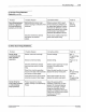
Table
6.
1 PC40 Service Equipment
Item
Number Part Number
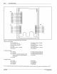
154 820
1 972
801
2 972 547
3 972
800
4
5
6
7
981
524
981
525
114 875
146 379
134
789
116 566
117 896
131 473
131 486
131
474
131 475
131
476
145 278
145 279
145 974
Description
PC40 AC Timer, 240V
• 8·pin
connector, right
• 12-pin connector
• 8-pin connector, left
• Truss head screw, #4-40x1.5 in.
• Truss head screw, #4-40x2 in.
Fuse,5A,250V
Back Enclosure
Remote Memory Select Switch, 4 Position (I)
Knob <
2
>
Keyed Lock
Out
Switch, DPDT
Emitter
for
Opposed Mode {Through-beam) Sensor
Receiver for Opposed Mode {Through-beam) Sensor
Retroreflective Sensor
Polarizing
Retrorefleclive Sensor
Diffuse Mode Sensor
Bifurcated Fiber Optic Cable <
3
>
Replacement Cover for Diffuse Mode Sensor <
4
>
Lens Kit <
5
>
(I)
Also order Knob, PIN 116 566.
C
2
l Required with Remote Memory Select Switch, PIN 134 789.
Qty.
Req'd.
Ref
1
1
1
2
4
1
Ref
Ref
Ref
Ref
Ref
Ref
Ref
Ref
Ref
Ref
Ref
Ref
<
3
> Required to convert Diffuse Mode Sensor, P/N
131
476, to fiber optic operation. Also, order Replacement
Cover, P/N 145 279.
<
4
> Required wi
th
Bifurcated Fiber Optic Cable, PIN 145 278.
<
5
> Provides fiber optic retro-reflective capability for Diffuse Mode Sensor, P/N 131 476.
C
Nordson
Corpor
a
~on
1994
An R
•g
hts R
es
erved
PIN
1083696
57·28
4
/94