
Operating instructions


1--
~-----
I
[ID---'
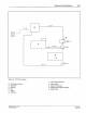
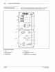
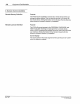
Figure
2.2-
PC
40
block diagram
B - PC40 Pattern Control
C - Applicator
D
-Solenoid
£-Gun
F-
Trigger
G - Substrate
C Nordson Cotporation 1993
AI Righls Resetved
B
l
I I
c
--2
Equipment Familiarization 2·3
4--
ro
s--
Jrr=r-·
--
~s=
I
I
I
G
I
--
\
I
I
1
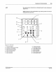
-Inp
ut voltage {240 VAC)
2 - Trigger signal
3 - Input air to solenoid
F
4 - Electrical input signal to solenoid
5-
Material flow
PIN
108
389A
57
·
28
1/93