
Operating instructions

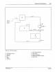

Figure
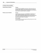
2.
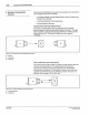
7 - Retroreflect
iv
e sensor
A - Emitter/Rece
iv
er
B
-Substrate
C - Retroreflector
()
Nordson Corporaoon 1993
AI Righls Reserved
Equipment Familiarization 2-7
Retroreflectlve
Sensors
This sensor consists
of
a single unit
that
contains the LED light source
(emitter) and the light-sensing phototransistor (receiver). The
emitter/receiver bounces its light off an opposing retroreflector
or
reflective tape and "sees" the reflected light.
The
light beam is broken
as
the substrate passes between the sensor unit and the reflector
(Figure 2.7).
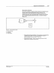
• Retroreflective Polarizing Model - This
ant
i-glare unit polarizes the
emitted light and filters out unwanted reflections.
It has an
effective range
of
2 in. (5.1 em) to
7ft
(2.1 m).
• Retroreflective Model - This is a non-polarized sensor that is
effective
up
to a range
of
15ft
(4.5 m).
PIN 108
389A
57
-28 1/93