
Operating instructions

Connecting
AC
Power to the
PC40ACUnit
(continued)
A
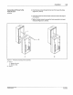
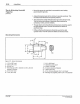
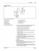
Figure 3.
7-
Temporary mounting
of
front assembly
A -
ViewA
1 - Stand-off
{1
of
2)
2 -
Screw
{1
of
2)
8 -
ViewB
0 NotdSon
Corpora~on
1993
AI
Rognts ResetVed
Installation 3-9
d. Push the two screws through the top two front assembly holes
(Figure 3.7, view A).
e.
Insert the screws into the two back enclosure stand-offs (Figure
3.7, view A).
f.
lighten
the two screws
to
secure the front assembly
to
the back
enclosure (Figure 3.7, view
8).
B
PIN
108
389
A
57· 28 1/93