
Operating instructions

Installation 3-11
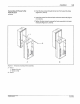
Connecting AC Power
to
the
PC40AC Unit
5. If you are connecting other devices
at
this time, proceed to the
app
ro
priate installation procedure(s)
in
this section.
(continued)
P2
P2-1
P2
-2
P2
- 3
P2
-4
P2
-5
P2
-6
P2
-7
P2
-B
P2
-9
P2-10
P2-11
P2
-
12
P1
P1-1
P 1
-2
P1
- 3
P1
-4
P 1
-5
P1
· 6
P1·7
P1
· 8
n.
I
0
r--
&
&
&
&
&
&
&
&
&
&
&
&
....._
....---
&
&
&
&
&
&
&
&
'-
-
llr
r--
&
&
&
&
&
&
&
&
'-
L/
0
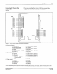
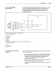
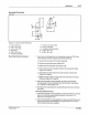
Figure 3.
9-
PC
40
240
V
AG
Model terminal block connections
P2
(Power and Outputs):
P2-1
(
AC
240V L1)
P
2-2
(AC 240V
Neut
ral)
P2·3 (
AC
Safety Ground) (
1
)
P2-4 (
NC
)
P
2-
5 (Valve 1 Return - Ne
utr
al)
P2-6 (Valve
1)
P1 (Remote Co
nt
rol):
P1-1 {Shield}
P1
-2
(Ground)
P
1-
3 (
Common-
co
nn
ect to
G
ro
und
or + 12V)
PT
-4
(
Lo
ck)
P4 (Trigger Inputs):
P4-1 (+12V)
P4
-2 (Trig
ge
r 1)
P4-3 (Gr
ound
)
P4-4 (Shi
el
d)
P
2-7
(Valve 2 Retu
rn
- Neutral)
P2-8
(V
alve 2)
P
2·9
(Valve 3 Retu
rn
- Ne
utr
al)
P2
-10 (Valve 3)
P
2-
11
(V
alve 4 Return - Ne
utr
a
l)
P2-12
(V
alve 4)
P
f-5
(Remote Memory S
el
ect 3)
P1-6 (Remote Me
mory
Se
lect
2)
P1-7 (Remote
Me
mo
ry
Sel
e
ct
1)
P1-8 (+12V)
P4-5 (+12V)
P4
-6
(T
rigg
er
2)
P4-7 (Gro
und
)
P4
-8 (Shield}
p
4
P4-1
P4-2
P4·3
P4
· 4
P4
· 5
P4-6
P4-7
P4-B
(
1
) Join multiple safety gr
ou
nds (as from several
AC
solenoids) with a connecto
r.
wire
nut
, etc.
be
fo
re connecting them to P2-3.
Cl
NO<
cls
oo
Co
rporauon 1994
All
R
ighC
s
Rese<ved
PIN 1
08
3898
57·
28
•
1'9
•