
Operating instructions

3-14 /nstalfation
Gun Solenoid Wiring
(ccntin
ued)
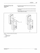
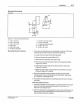
5.
If
you are
NOT
connecting other devices
at
this time, do the following:
a. Grasp the front assembly with one hand. Remove the two screws
holding it
to
the back enclosure.
b. Carefully rotate
the
front assembly
1so•
and place it
on
the back
enclosure.
c. Replace and tighten the two loose screws.
d.
lighten
the four remaining screws.
6.
If
you are connecting other
dev
ices at this time, proceed-to the
appropriate installation procedure(s) in this section.
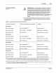
8.
Trigger
(Sensor) Installation
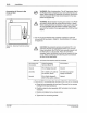
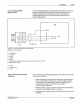
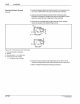
Trigger Input Pin Characterization The trigger devices, usually photosensors, are connected to PC40
terminal block P4 (ref
er
to
Table 3.6 and see Figure 3.9). The signals
from the trigger are resistively coupled and filter
ed
into the PC44.
P
iN
108
3
89A
5
7-2
8 1/93
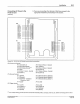
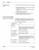
Tab
le 3.
6-
Tr
i
gger
Pin Characterization
Terminal
Block-Pin
Connection
Trigger
#1
P4
-1 ("+12V")
P4
-2 ("TRIGGER 1")
P4
-3 ("GROUND")
P4-4 ("SHIELD")
Trigger
#2
(if
used),
P4-5
("
+ 12V")
P4-6 ("TRIGGER 2")
P4
-7 ("GROUND")
P4-8 ("SHIELD")
Function
DC
power for first trigger. Maximum current available
from + 12 V is
500
mA
. This is the maximum current
ava
il
able for all connections
to
+ 12 V including those
loads
on
other PC40 connectors.
Input signal from first trigger.
Ground connection for first trigger.
Shield connection for first trigger.
DC power for second trigger. Maximum current
available from + 12 V is
500 rnA. This is the maximum
current available for all connections to + 12 V including
those loads on other
PC40 connectors.
Input signal from second trigger.
Ground for second trigger.
Shield connection for second trigger.
C>
Nordson Corpora1ion 1993
AJI
A
ogh1s
Aeurv
ed